
Page 928 - Industrial Power Engineering and Applications Handbook
P. 928
281878 Industrial Power Engineering and Applications Handbook
100 7 N 6.35 S
S=lOO 100
I
b= 10.
l
a d k
a = 6.35
b = 101.60 A// dimensions in mm.
s = 100.00 a = 44.45
b = 101.60
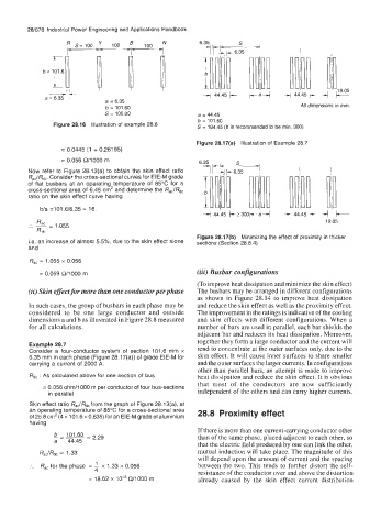
Figure 28.16 Illustration of example 28.6 S = 184.45 (It is recommended to be min. 300)
Figure 28.17(a) Illustration of Example 28.7
= 0.0445 (1 + 0.26195)
= 0.056 CY1000 m
Now refer to Figure 28.13(a) to obtain the skin effect ratio
Rac/Rdc. Consider the cross-sectional curves for EIE-M grade
of flat busbars at an operating temperature of 85°C for a
cross-sectional area of 6.45 cm2 and determine the R,,/Rdc
ratio on the skin effect curve having
b/a =101.6/6.35 = 16.
.. = 1.055
'
RdC
Figure 28.17(b) Minimizing the effect of proximity in thicker
Le. an increase of almost 5.5%, due to the skin effect alone sections (Section 28.8.4)
and
R,, = 1.055 x 0.056
= 0.059 WOO0 m (iii) Busbar configurations
(To improve heat dissipation and minimize the skin effect)
(ii) Skin effect for more than one conductorperphase The busbars may be arranged in different configurations
as shown in Figure 28.14 to improve heat dissipation
In such cases, the group of busbars in each phase may be and reduce the skin effect as well as the proximity effect.
considered to be one large conductor and outside The improvement in the ratings is indicative of the cooling
dimensions a and b as illustrated in Figure 28.8 measured and skin effects with different configurations. When a
for all calculations. number of bars are used in parallel, each bar shields the
adjacent bar and reduces its heat dissipation. Moreover,
together they form a large conductor and the current will
Example 28.7 tend to concentrate at the outer surfaces only, due to the
Consider a four-conductor system of section 101.6 mm x
6.35 mm in each phase (Figure 28.17(a)) of grade EIE-M for skin effect. It will cause inner surfaces to share smaller
carrying a current of 2000 A. and the outer surfaces the larger currents. In configurations
other than parallel bars, an attempt is made to improve
Rdc : As calculated above for one section of bus heat dissipation and reduce the skin effect. It is obvious
that most of the conductors are now sufficiently
= 0.056 ohm/l000 m per conductor of four bus-sections independent of the others and can carry higher currents.
in parallel
Skin effect ratio R,,IRd, from the graph of Figure 28.13(a), at
an operating temperature of 85°C for a cross-sectional area 28.8 Proximity effect
of 25.8 cm2 (4 x 101.6 x 0.635) for an EIE-M grade of aluminium
having
If there is more than one current-carrying conductor other
than of the same phase, placed adjacent to each other, so
that the electric field produced by one can link the other,
R,JRd, 5 1.33 mutual induction will take place. The magnitude of this
will depend upon the amount of current and the spacing
:. R,, for the phase = 1 1.33 x 0.056 between the two. This tends to further distort the self-
x
4 resistance of the conductor over and above the distortion
= 18.62 x 10-~ CY1000 m already caused by the skin effect current distribution