Page 919 - Industrial Power Engineering and Applications Handbook
P. 919
Carrying power through metal-enclosed bus systems  28/869

       28.4.2  Electrodynamic effects                 2  Altitude
                                                      3  Atmospheric conditions and
       The short-circuit current is generally unsymmetrical and   4  Excessive vibrations and seismic effects
       contains a d.c. component, Zdc,  as discussed  in Section
       13.4.1(7). The d.c. component, although it lasts for only
       three  or four  cycles,  creates  a  sub-transient  condition   28.5.1  Ambient temperature
       and causes excessive electrodynamic forces between the
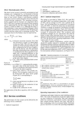
       current-carrying  conductors.  The mounting  structure,   The ratings  as provided  in Tables 30.2,  30.4 and  30.5
                                                      and others refer to an ambient temperature, with a peak
       busbar supports and the fasteners are subjected to these   of  40°C  and  an  average of  35°C  over  a period  of  24
       forces. This force is greatest at the instant of fault initiation   hours. The end temperature for aluminium is considered
       and is represented  by  the first  major  loop of  the fault   safe at 85-90°C,  at which the metal does not deteriorate
       current, as noted in Table 13.1 1. Although this force is   (oxidize) or change its properties (mechanical strength)
       only momentary, it may cause permanent damage to these   over a long period of  operation. Figure 28.9 shows the
       components and must be considered when designing the   effect of higher operating temperatures on the mechanical
       current-carrying system and its mounting structure. The   strength  of  aluminium  metal.  The  oxidation  and
       maximum force in flat busbars may be expressed by
                                                      mechanical  strength are two vital  factors  that need be
              16.Z:                                   borne in mind when  selecting busbar size to ensure its
       F,,,  =k.-   x 104N/m                  (28.4)   adequacy during long hours of continuous operation. Table
                S                                     28.2 lists the permissible operating temperatures of the
       where                                          various parts of  a bus system.
              F,  = estimated  maximum  dynamic force that   For  higher  ambient  temperatures,  current  capacity
                  may develop in a single- or a three-phase   should  be  suitably  reduced  to  maintain  the  same end
                  system on a fault. This will vary with the   temperature during continuous operation. Refer to Tables
                  number of current-carrying conductors and   28.3(a) and (b), recommending the derating factors for a
                  their configuration but for ease of applica-   higher ambient temperature or a lower temperature rise
                  tion  and for brevity  only the  maximum   for the same end temperature of 85" or 90°C respectively.
                  force that will develop in any configuration   For intermediate ambient temperatures, see Figure 28.10.
                  is considered in the above equation. It will
                  make  only  a  marginal  difference  to the
                  calculations, but it will be on the safe side.   Table 28.2  Operating temperature of a bus system
                  For more details refer to the further reading
                  at the end of the chapter.          Maximum operating  temperature   Maximum
              Zsc = r.m.s. value of the symmetrical fault current   (hot spot)        temperature
                  in amperes                                                          limit as in
      Factor of                                                                       IEEE- C-3 7-2P
       asymmetry  = as in Table 13.11, representing the momen-
                  tary peak value of the fault current. This   Bus conductor with plain connection joints   70°C
                  factor is considered in the numerical factor   Bus conductor with silver plated or   105°C
                                                        welded contact surfaces
                  16 used in the above equation.
               k = space factor, which is  1 for circular con-   Enclosure
                  ductors. For rectangular conductors it can   Accessible part         80°C
                  be  found  from  the  space  factor  graph   Non-accessible part     110°C
                  (Figure 28.7) corresponding  to       Termination at cables with plain connections  70°C
                                                        Termination at cables with
                                                        silver-surfaced or equivalent connections   85OC
                  S-a where
                   a+b                                aOr as specified by the user.
               S = centre spacing between two phases in mm
                  (Figure 28.8)                       Note
               a = space occupied by the conductors of  one   For temperatures  above  100°C it  is  recommended to use  epoxy
                                                      insulatorslsupports, which can continuously operate up to 125°C.
                  phase in mm, and                    SMC/FRP (fibreglass reinforced plastic) insulatorslsupports may
               b = width of the conductors in mm.     not withstand 105'C.
       For application of the above equation, refer to Example
       28.12.                                         Operating temperatures of bus conductors

       28.5  Service conditions                       Aluminium and copper conductors start oxidizing at about
                                                      90°C. The oxides of aluminium (A120) and copper (CuO)
                                                      are poor conductors  of  electricity, They may adversely
       The performance of a bus system can be affected by the   affect bus conductors, particularly at joints, and reduce
       following service conditions:                  their  current-carrying  capacity  over  time,  and lead  to
                                                      their overheating, even to an eventual failure. Universal
       1  Ambient temperature                         practice therefore is to restrict the operating temperature

