
Page 915 - Industrial Power Engineering and Applications Handbook
P. 915
28/866 Industrial Power Engineering and Applications Handbook
VP 99 gg gg
Mia/ temperature 8 a $j wr- dN
‘““Jr-
A
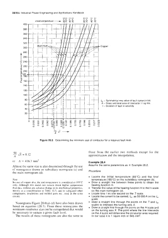
Figure 28.5 Determining the minimum size of conductor for a required fault level
those from the earlier two methods except for the
Ji = 0.12 approximation and the interpolation.
or A = 416.7 mm2 Example 28.4
Assume the same parameters as in Example 28.2.
Almost the same size is also determined through the use
of nomograms drawn on subsidiary nomogram (c) and Procedure
the main nomogram (d).
Locate the initial temperature (85°C) and the final
Note temperature (185°C) on the subsidiary nomogram (b).
In case of copper also, the end temperature is considered at 18S’C Draw a straight line between these points to obtain the
only. Although this metal can sustain much higher temperature heating function H.
than this, without any adverse change in its mechanical properties, Transfer the value of the heating function H to the H scale
merely as a consideration to Table 32.3, and to safeguard other on the main nomogram (d).
components, insulations and welded parts etc., used in the same Locate time t as one second on the T scale.
circuit. Locate the current to be carried, Is,, as 50 000 A on the I,,
scale.
Nomograms Figure 28.6(a)-(d) have also been drawn Draw a straight line through the points on the T and I,,
based on equation (28.1). From these nomograms the scales to intersect the turning axis X.
Draw a straight line through the points on the H scale and
minimum conductor size can be extrapolated that would on the turning axis X. The point where the line intersects
be necessary to sustain a given fault level. on the A scale will determine the conductor area required.
The results of these nomograms are also the same as In our case it is 1 squre inch or 645 mm2.