Page 910 - Industrial Power Engineering and Applications Handbook
P. 910

Carrying power through metal-enclosed bus systems  28/861
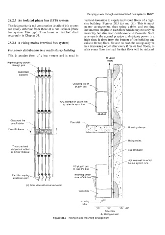
      28.2.3  An isolated phase bus (IPB) system     vertical formation to supply individual floors of a high-
                                                     rise  building  (Figures  28.3 (a) and  (b)). This is  much
      The design criteria and construction details of this system   neater  arrangement  than  using  cables  and  running
      are totally  different from those of  a non-isolated  phase   innumerous lengths to each floor which may not only be
      bus  system.  This  type  of  enclosure  is  therefore  dealt   unwieldy but also more cumbersome to terminate. Such
      separately in Chapter 3 1.                     a system is the normal practice to distribute power in a
                                                     high-riser.  It rises from the bottom of  the building  and
      28.2.4  A  rising mains (vertical bus system)   runs to the top floor. To save on cost, the ratings may be
                                                     in a decreasing order after every three or four floors, as
      For power distribution in a multi-storey building   after every floor the load for that floor will be reduced.
      This  is  another  form of  a  bus  system  and  is  used  in
                                                                  To  upper
                                                                   floors
      Rigid coupling straight
                   -'f
             supports -
         through joint
            SMC/DMC
                                                            rl
                                              Outgoing tap-off
                                                plug-in box


                                      O/G distribution board (DB)
                                        to cater for each floor


        Glasswool fire                       Floor slab  -,
        proof barrier  1                              i
                 Y                 I                        b   *
      Floor thickness                                                           Mounting clamps


                                                                                 Rising mains
        stoppers of  rubber -                                                   Bus conductor
         Thrust pad and
        or similar material

                                                                                High riser wall on which
                                                                                the bus system runs
                                               I/C plug-in box
                                               to feed the bus
         Flexible coupling -                   Incoming switch
         expansion joint                       fuse MCCB box  d

                  (a) Front view with cover removed
                                                  Cable box


                                                   Incoming
                                                    cable
                                                                               GF
                                                                  Side view
                                                                (b) Rising on wall
                                  Figure 28.3  Rising mains mounting arrangement
   905   906   907   908   909   910   911   912   913   914   915