
Page 913 - Industrial Power Engineering and Applications Handbook
P. 913
28/864 Industrial Power Engineering and Applications Handbook
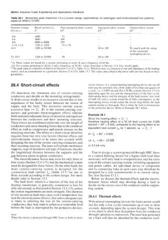
Table 28.1 Momentary peak (maximum r.m.s.) current ratings, asymmetrical, for switchgear and metal-enclosed bus systems,
based on ANSI-C-37/20C
Nominal voltage Rated current (Ir) Non-begregated phase cjstenz Segregated phase sxstem Icolrited phase osteiii
kV(Km.s.) A" kAh kA" kA
~ ~~~ ~ ~~
0.6 I600 75 - -
0.6 3000 100 - -
0.6 4000 to 6000 I50 ~ -
4.16-13.8 1200 to 3000 19 to 78 - -
14.4 I200 to 20 000 - 60 to 190 To match with the iating
of the connected
interrupting device
23-34.5 1200 to 20 000 58 60 to 190
._ ~~
a (i) These values are based for a system, pertaining to series I1 and a frequency of 60 Hz.
(ii) For systems pertaining to Series I and a frequency of 50 Hr, values furnished in Section 13.4.1(4). would apply.
The peak value is a function of fault level Section 13.4.1 (7), ydbk 13.1 I. Which in turn, is a function of size and impedance of the feeding
source, such as a transformer or a generator, Section 13.4. I (S), Table 13.7. The values prescribed in the above table are thus based on thehe
parameters.
28.4 Short-circuit effects circuit release\ of a current limiting interrupting device the cut-off
time may be extremely low, of the order of less than one quarter of
a cycle, i.e. < 0.005 second (for a SO Hz system) (Section 13.5.1)
(To determine the minimum size of current-carrying depending upon the size and the characteristics of the fuse? or the
conductors and decide on the mounting arrangement). interrupting device and the intensity of the fault current. Any level
A short-circuit results in an excessive current due to low of fault for such a system would be of little consequence, a5 the
impedance of the faulty circuit between the source of interrupting device would isolate the circuit long before the fault
supply and the fault. This excessive current causes current reaches its first peak. This is when the fault is downstream
excessive heat (= IC', . R) in the current-carrying con- of the protective device. Refer to Example 28.1 below.
ductors and generates electromagnetic effects (electric
field) and electrodynamic forces of attraction and repulsion Example 28.1
between the conductors and their mounting structure. Since the heating effect = I$ . t
These forces are distributed uniformly over the length of therefore heating effect of a 50 kA fault current for 0.005
second = 50' x 0.005, compared to the heating effect of an
conductors and cause shearing forces due to the cantilever equivalent fault current I,, for 1 second, i.e. -
effect as well as compressive and tensile stresses on the . 1
mounting structure. The effect of a short-circuit therefore
requires these two very vital factors (thermal effects and or /& = 50' x 0.005
electrodynamic forces) to be taken into account while i.e I,, = 50 x liooos
designing the size of the current-carrying conductors and
their mounting structure. The latter will include mechanical or 3.5 kA only
supports, type of insulators and type of hardware, besides
the longitudinal distance between the supports and the Thus to design a system protected through HRC fuses
gap between phase-to-phase conductors. or a current limiting device for a higher fault level than
The electrodynamic forces may exist for only three or necessary will only lead to overprotection and the extra
four cycles (Section 13.4.1 (7)), but the mechanical system cost of the current-carrying.system, switching equipment
must be designed for these forces. On the other hand, the and power cables. An individual device or component
main current-carrying system is designed for the and its connecting links in such cases may therefore be
symmetrical fault current, I,, (Table 13.7) for one or designed for a size commensurate to its current rating.
three seconds according to the system design. For more See also Section 13.5.1.
details refer to Section 13.5. Below we discuss the thermal effects and the electro-
The fault level, which is a function of the size of the dynamic forces which may develop during a fault to
feeding transformer, is generally considered to last for decide on the correct size of the conductor and its suppor-
only one second, as discussed in Section 13.4.1(5), unless ting system.
the system requirements are more stringent. This duration
of one second on fault may cause such a temperature rise 28.4.1 Thermal effects
(not the electrodynamic forces), that unlcss adequate care
is taken in selecting the size of the current-carrying With normal interrupting devices the fault current would
conductors, they may melt or soften to a vulnerable level last for only a few cycles (maximum up to one or three
before the fault is interrupted by the protective devices. seconds, depending upon the system design). This time
is too short to allow heat dissipation from the conductor
Nute through radiation or convection. The total heat generated
When the circuit is protected through HRC fuses or built-in short- on a fault will thus be absorbed by the conductor itself.