
Page 911 - Industrial Power Engineering and Applications Handbook
P. 911
28/862 Industrial Power Engineering and Applications Handbook
(say, after every 7.5-10 m) to absorb the expansion
of busbars on load.
28.2.5 An overhead bus (horizontal bus system)
Unlike a high riser, now the overhead bus system runs
horizontally, below the ceiling at a convenient height, as
shown in Figure 28.4(c) to distribute power to light and
small load points. A large tool room or a machine shop
are installations that would otherwise require a distribution
system, for short distances, to meet the needs of various
load points and make power distribution unwieldy and
cumbersome. Moreover, it would also mean running many
cables under the floor to feed each load point. In an
overhead busbar system, the power can be tapped from
any number of points to supply the load points just below
it through a plug-in box similar to that used on a rising
mains. The floor can now be left free from cables and
trenches.
28.3 Design parameters and service
conditions for a metal-enclosed
bus system
28.3.1 Design parameters
A bus system would be designed to fulfil the following
parameters.
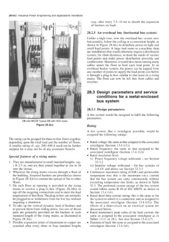
DB with MCCB Typical DB with HCC fuses
Figure 28.3(c) Rating
A bus system, like a switchgear assembly, would be
assigned the following ratings:
The rating can be grouped for three or four floors together,
depending upon the total load and the number of floors. Rated voltage: the same as that assigned to the associated
A smaller rating of, say, 200-400 A need not be further switchgear (Section 13.4.1( 1))
stepped for it may not be of any economic benefit. Rated frequency: the same as that assigned to the
associated switchgear (Section 13.4.1(2))
Special features of a rising mains Rated insulation level
(i) Power frequency voltage withstand - see Section
They are manufactured in small standard lengths, say, 32.3.2
1.8-2.5 m, and are then joined together at site to fit (ii) Impulse voltage withstand - for bus systems of
into the layout. 2.4 kV and above see Section 32.3.3
Wherever the rising mains crosses through a floor of Continuous maximum rating (CMR) and permissible
the building, fireproof barriers are provided as shown temperature rise: this is the maximum r.m.s. current
in Figure 28.3(b) to contain the spread of fire to other that the bus system can carry continuously without
floors. exceeding temperature rise limits, as shown in Table
On each floor an opening is provided in the rising 32.3. The preferred current ratings of the bus system
mains to receive a plug-in box (Figure 28.3(b)) to would follow series R-10 of IEC 60059, as shown in
tap-off the outgoing connections and to meet the load Section 13.4.1(4).
requirement of that floor. The plug-in box can normally Rated short-time current rating: this is the same as for
be plugged in or withdrawn from the live bus without the system to which it is connected, and as assigned to
requiring a shutdown. the associated switchgear (Section 13.4.1(5)). The
To take up the vertical dynamic load of busbars and effects of a short-circuit on an electrical system are
to prevent them from sliding down, two sets of thrust discussed below.
pads are generally provided on the busbars in each Rated momentary peak value of the fault current: the
standard length of the rising mains, as illustrated in same as assigned to the associated switchgear as in
Figure 28.3(a). Tables 13.11 or 28.1. See also Section 13.4.1(7).
Flexible expansion joints of aluminium or copper are Duration of fault: the same as assigned to the associated
essential after every three or four standard lengths switchgear (Section 13.4.1(6).