
Page 934 - Industrial Power Engineering and Applications Handbook
P. 934
28/884 Industrial Power Engineering and Applications Handbook
this particular instance, one may reduce the content of +
R
X, by reducing S if permissible, or consider the next
higher cross-section of busbars. This size of bus section,
in this particular instance, may be considered for a current
rating up to 800 A.
Example 28.9
Consider Example 28.7 to determine the effect of proximity:
(i) For the configuration of Figure 28.17(a)
a - 44.45 - 0.4375
b 101.60
S
1.26 - = 1.26 x 184.45 ~ 1.59
a+b 44.45 + 101.60
then X,, due to the proximity affect from the graph of Figure
28.24,
= 125Wm
or 0.125C2/1000 m per phase and
(ii) impedance, z= d0.0186' + 0.125'
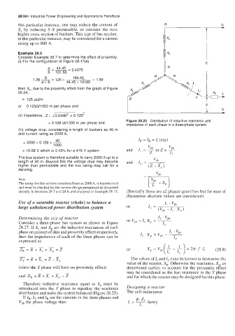
Figure 28.25 Distribution of inductive reactance and
= 0.126 R/1000 m per phase and
impedance of each phase in a three-phase system
(iii) voltage drop, considering a length of busbars as 40 m
and current rating as 2000 A,
40 I, = I, = I, (say)
1000
= 2000 x 0.1 26 x ~
= 10.08 V which is 2.43% for a 415 V system
The bus system is therefore suitable to carry 2000 A up to a
length of 40 m. Beyond this the voltage drop may become
higher than permissible and the bus rating may call for a
derating.
Note
The rating for this section considered here as 2000 A, is hypothetical
and must be checked for the various design parameters as discussed
already, in Sections 28.5 and 28.6, and analysed in Example 28.12. (Basically these are all phasor quantities but for ease of
illustration absolute values are considered)
Use of a saturable reactor (choke) to balance a
large unbalanced power distribution system
Determining the size of reactor I, . Vph
Consider a three-phase bus system as shown in Figure or Vph -I, X, = -
I,
28.27. If X, and X are the inductive reactances of each
phase on account of skin and proximity effects respectively, I, ' vph
then the impedances of each of the three phases can be I, . xp = Vph - -
I,
expressed as
2,=R+X,+X,=Z or
The values of I, and I, must be known to determine the
value of the reactor, Xp. Otherwise the reactance, X,, as
(since the Y phase will have no proximity effect) determined earlier, to account for the proximity effect
may be considered as the lost reactance in the Y phase
and for which the reactor may be designed for this phase.
Therefore inductive reactance equal to Xp must be
introduced into the Y phase to equalize the reactance Designing a reactor
distribution and make the system balanced (Figure 28.25). The self-inductance
If IR, Iy and IB are the currents in the three phases and
Vph the phase voltage then