
Page 938 - Industrial Power Engineering and Applications Handbook
P. 938
28/888 Industrial Power Engineering and Applications Handbook
28.8.4 Minimizing the proximity effect Electric field
1 Maintaining greater spacing (S) between
the phases
This can be done by providing adequate clearances
between the conductors and the inside of the enclosure Iti
(say, 300 mm). Table 30.5 and all the other tables in
Chapter 30 are based on the fact that the proximity effect
is almost negligible at 300 mm from the centre of the 1- 1st group 2nd group -!
Current-carrying conductors. But in thicker sections, or (a) Interleaving of 2 conductors per phase
where a number of smaller sections are used together to
form a phase, the current will concentrate at the outer 2 300 rnrn preferably
surfaces only (skin) rather than the nucleus. Therefore,
to achieve an almost Lero-proximity efrect condition it is R YiB N R YIB N R Y
desirable to provide a space of 300 mm and more between li i
the extreme outer surfaces, rather than between the centres,
as shown in Figure 28.17(b). The condition of S 2 4b
(Table 28.7) will also be almost satisfied by doing so. 1- 1st group 2nd group 4
For still higher currents, this distance must be increased
further or a segregated construction adopted (Section (b) Interleaving of 4 conductors per phase
28.2.2). But to keep the phase conductors completely
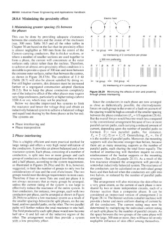
Figure 28.29 Minimizing the effects of skin and proximity
out of the inductive effect of the other phases may require through phase interleaving
very large enclosures, particularly at higher ratings (above
3200 A or so), which may not be practical. Since the conductors in each phase are now arranged
Below we describe improvised bus systems to limit
as close as dielectrically possible, the electrodynamic
the reactance and hence the voltage drop and obtain an forces on each group in the event of a fault on account of
inductively balanced system to achieve a balanced voltage the spacing would be high as a result of the smaller spacing
and equal load sharing by the three phases at the far end. between the phase conductors (F, ~c I/S equation (28.4)).
The systems are
But the overall forces would become much less compared
to the conventional arrangement because of two or more
0 Phase interleaving and parallel current paths, each carrying a reduced amount of
0 Phase transposition current, depending upon the number of parallel paths so
formed. Fc.r two parallel paths, for instance,
2 Phase interleaving F,, = 2 . ( I:c /2) or = I; /2. Generalizing, F,,, -, l/n if
n is the number of parallel paths. Moreover, the mounting
This is a highly efficient and more practical method for supports will also become stronger than before, because
large ratings and offers a very high metal utilization of there are as many mounting supports as the number of
the conductors. It provides an almost balanced and a low parallel paths, each sharing the total force equally. The
reactance system. Each phase, consisting of a number of method of interleaving will therefore require no extra
conductors, is split into two or more groups and each reinforcement of the busbar supports or the mounting
group of conductors is then rearranged into three or three structures. (See also Example 28.1 1). As a result of the
and a half phases, according to the system requirement, low reactance obtained the arrangement will provide a
as illustrated in Figures 28.29(a) and (b). It is, however, somewhat inductively balanced system. The reactance of
suggested, to limit the number of groups to only two for the conductors can be calculated on an individual group
considerations of size and the cost of enclosure. The two basis and then halved when the conductors are split into
groups would meet the design requirements in most cases. two halves, or reduced by the number of parallel paths
Therefore if four or more flats are used per phase it is arranged.
not always necessary that as many groups be arranged, The arrangement will also minimize the skin effect to
unless the current rating of the system is too large to a very great extent, as the current of each phase is now
effectively reduce the reactance of the entire system. In shared by two or more independent circuits, each of a
four conductors, for instance, two groups, each with two thinner section than a composite phase. It can be
conductors per phase, can be arranged as shown in Figure considered an improvised version of arrangement 2 in
28.29(b) to achieve a low reactance system as a result of Figure 28.14. The thinner sections (smaller nucleus) will
the smaller spacings between the split phases, on the one provide a better and more uniform sharing of current by
hand, and two parallel paths, on the other. The two parallel all the conductors. The current rating may now be
paths will further reduce the total reactance to one half. determined by multiplying the individual current rating
The field produced by each split phase would now become of each split phase by the number of parallel circuits. As
half (@ = I) and fall out of the inductive region of the the space between the two groups of the same phase will
other. The arrangement would thus provide a system now be large, 300 mm or more, they will have nil or only
with a low proximity effect. negligible influence of skin effect among themselves.