
Page 937 - Industrial Power Engineering and Applications Handbook
P. 937
Carrying power through metal-enclosed bus systems 28/887
Proximity effect on non-isoluted bus systems The electrodynamic forces between the enclosure and
the conductors will be small because the enclosure, which
Drawing inferences from the literature available on the is non-continuous, will carry much less current than the
subject (see the further reading at the end of the chapter), main conductors. They therefore need not be considered
based on laboratory tests, practical experience and the separately, as the metallic structure will have sufficient
field data available, deratings for different configurations strength to bear them.
are shown in Table 28.7 which should be sufficient to In a non-magnetic enclosure, such as aluminium or
account for the likely proximity effects stainless steel, there will be only resistance losses. In a
magnetic enclosure, such as mild steel (MS), there will
Proximity eflect on the enclosure also be hysteresis and eddy current losses in addition to
resistance losses. All these losses appear as heat in the
The electric field produced by the current-carrying enclosure and the metallic structures in the vicinity. At
conductors of each phase also links the metallic bus higher currents say, 2000 A and above, this phenomena,
enclosure, its mounting supports, and structures existing particularly with MS enclosures, may assume such large
in the vicinity, parallel and around the axis of the current- proportions that the enclosure, instead of providing a
carrying conductors. It causes induced (parasitic) currents heat-dissipating surface to the heat generated by the
in such structures and leads to the following: current-carrying conductors inside, may add to their heat.
Depending upon the current rating, the configuration of
0 Resistance losses (Z'R) and the busbars and the material of the enclosure should be
Magnetic losses. chosen to minimize these effects as far as possible. It is
possible to do this by adopting one or more of the following
Magnetic losses will constitute the following: methods. Since the spacing in an HT system is already
large, an HT system is generally not affected by the
Eddy current losses (= B2, Section 1.6.2.A-iv) and proximity effects. The following discussion therefore
0 Hysteresis losses (= B'.6, Section 1.6.2.A-iv) relates primarily to an LT system.
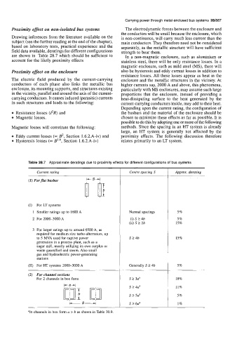
Table 28.7 Approximate deratings due to proximity effects for different configurations of bus systems
Current rating Centre spacing S Approx. derating
(1) Forflat busbar
(I) For LT systems
1 Smaller ratings up to 1600 A Normal spacings 5%
2 For 2000-3000 A (i) S 2 4b 5%
(ii) S 2 2b 15%
3 For larger ratings up to around 6500 A, as
required for medium size turbo-alternators, up
to 5 MVA used for captive power S 2 4b 15%
generation in a process plant, such as a
sugar mill, mostly utilizing its own surplus or
waste gasedfuel and steam. Also small
gas and hydroelectric power-generating
stations
(11) For HT systems 2000-3000 A Generally S t 4b 5%
(2) For channel sections
For 2 channels in box form s 2 3a" 18%
--- S24aa 11%
s 2 5aa
5%
'In channels in box form a > b as shown in Table 30.9. S 2 6aa 1%