
Page 944 - Industrial Power Engineering and Applications Handbook
P. 944
28/894 Industrial Power Engineering and Applications Handbook
:. Receiving side voltage of phases R and B (vii) Mechanical suitability of busbars and their
supporting system
Below we analyse the adequacy and the suitability of busbars,
- 415 13.9
6 fasteners and the insulators supporting the busbars, to
withstand the above forces acting differently at different
= 225.7 V locations.
Bending stresses on the busbars
41 5
and of phase Y = - 1.78
fi Bending stress at section x - x = 12.M.N = kg/cm'
(28.10)
= 237.8 V
where
The imbalance for this length and rating of bus system is F, = maximum electrodynamic forces acting on each support,
not substantial, yet if we assume that a balanced supply in the event of a fault, as calculated above = 514 kgf
source is desirable, then we must make up the lost inductance I = centre distance between two busbar supports = 40 cm
in phase Yby inserting a reactor into this phase, as discussed M = sectional modulus of each busbar at section x - x
in Section 28.8.2 of an equal value of X,, i.e. = 1 a. b' in cm3
6
50
X, =110~10-~ x-=0.0055R
1000
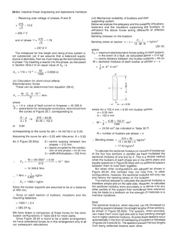
(vi) Calculation for short-circuit effects xl-
Electrodynamic forces
These can be determined from equation (28.4), x -
16. l& K. lo4 ! 1
F, = N/m
S
where
I,, = r.m.s. value of fault current in Amperes = 45 000 A
K = space factor for rectangular conductors, determined from where for a 152.4 mm x 6.35 mm busbar section
the curves of Figure 28.7, corresponding to a = 6.35 mm
b = 152.4 mm
S- a i,e,
- 210 - 44.45
a+b 44.45 + 152.4 , M= 1 6.35 x 152.4' cm3
6 1000
or 0.84
= 24.58 cm3 (as indicated in Table 30.7)
corresponding to the curve for alb = 44.45D52.4 or 0.29
N = number of busbars per phase = 4
Assuming the curve for alb = 0.25 with little error, K = 0.93
:. Bending stress = 514 40 kg/cm2
As in Figure 28.33(a) S =centre spacing between two 12 x 24.58 x 4
phases = 210 mm = 17.43 kg/cm2
a = space occupied by the conduc-
tors of one phase = 44.45 mm To calculate the sectional modulus (or moment of resistance)
b = width of the busbars = 152.4 mm of the four bus sections in parallel we have multiplied the
sectional modulus of one bus by 4. This is a simple method
:. F,,, = 16 x (45 000)' x 0.93 N/m when the busbars of each phase are in the same plane and
21 0 equally spaced as in Figure 28.33(a) with no additional spacers
between them to hold them together.
= 14 348.6 N/m But when other configurations are adopted as shown in
Figure 28.34, this concept may not hold true. In other
.. 1 N/m =- kgf/m configurations, however, the sectional modulus will only rise
9.807 and reduce the bending stress on the busbars.
:. F, - 1463.1 kgflm The method adopted to calculate the sectional modulus is
therefore simple and on the safe side. However, to calculate
Since the busbar supports are assumed to be at a distance the sectional modulus more accurately or to derive it for any
of 400 mm, other section of the support than considered here reference
may be made to a textbook on the strength of materials or a
:. force on each section of busbars, insulators and the machine handbook.
mounting fasteners
= 1463.1 x 0.4 Note
The sectional modulus, when required, can be increased by
= 585.24 kg providing spacers between the straight lengths of bus sections,
as shown in Figure 28.33(b). The spacers, when provided,
We have drawn a comparison of these forces for the other can make them more rigid and add to their bending strength
busbar configurations in Table 28.8 for more clarity. due to higher sectional modulus. At joints these spacers occur
Since Figure 28.34 is found to be a better arrangement, automatically in the form of overlapping of busbars or fishplates
we have considered forces as in this arrangement only in all (Figures 29.4 and 29.5). The spacers prevent the bus lengths
our subsequent calculations. from being deflected towards each other.