
Page 947 - Industrial Power Engineering and Applications Handbook
P. 947
FL Y R Y Carrying power through metal-enclosed bus systems 281897
2 x 8.54
a= 10
length
Bus
A=15
A= 15
I I I
I_ 210-15=214 e = 13
Side view Elevation
(All dimensions in mm)
Detail of each support
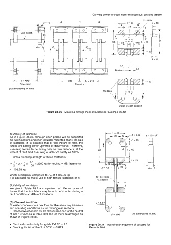
Figure 28.36 Mounting arrangement of busbars for Example 28.12
Suitability of fasteners
As in Figure 28.36, although each phase will be supported
on two insulators and each insulator mounted on 2 x M8 size
of fasteners, it is possible that at the instant of fault, the
forces are acting either upwards or downwards. Therefore,
assuming forces to be acting only on two fasteners, at the
instant of fault and assuming a factor of safety as 1 OO%,
Cross-breaking strength of these fasteners
x
= 1 2 x x 82 x 2200 kg (for ordinary MS fasteners)
2 4 100
= 11 05.28 kg
which is marginal compared to F,,, of 1189.36 kg.
It is advisable to make use of high tensile fasteners only.
Suitability of insulators
We give in Table 28.9 a comparison of different types of
forces that the insulators may have to encounter during a
fault condition at different locations.
(B) Channel sections 2 x 8.54
Consider channels in a box form for the same requirements
and operating conditions as for rectangular sections. -b@G$y
Choose two channels for the phases and one for the neutral
of size 127 mm as in Table 30.9 and let them be arranged as s= 100 (All dimensions in mm)
shown in Figure 28.38.
0 Electrical conductivity for grade E-91 E = 1 .O Figure 28.37 Mounting arrangement of busbars for
Derating for an ambient of 50°C = 0.815 Example 28.6