
Page 230 - Industrial Wastewater Treatment, Recycling and Reuse
P. 230
204 Industrial Wastewater Treatment, Recycling, and Reuse
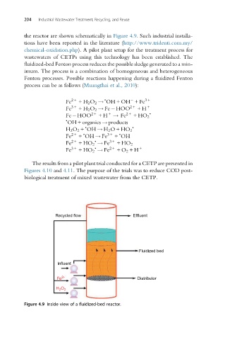
the reactor are shown schematically in Figure 4.9. Such industrial installa-
tions have been reported in the literature (http://www.tridenti.com.my/
chemical-oxidation.php). A pilot plant setup for the treatment process for
wastewaters of CETPs using this technology has been established. The
fluidized-bed Fenton process reduces the possible sludge generated to a min-
imum. The process is a combination of homogeneous and heterogeneous
Fenton processes. Possible reactions happening during a fluidized Fenton
process can be as follows (Muangthai et al., 2010):
•
Fe 2+ +H 2 O 2 ! OH + OH +Fe 3+
Fe 3+ +H 2 O 2 ! Fe HOO 2+ +H +
+
Fe HOO 2+ +H ! Fe 2+ +HO 2 •
•
OH + organics ! products
• •
H 2 O 2 + OH ! H 2 O+HO 2
•
•
Fe 2+ + OH ! Fe 3+ + OH
•
Fe 2+ +HO 2 ! Fe 3+ +HO 2
•
Fe 3+ +HO 2 ! Fe 2+ +O 2 +H +
The results from a pilot plant trial conducted for a CETP are presented in
Figures 4.10 and 4.11. The purpose of the trials was to reduce COD post-
biological treatment of mixed wastewater from the CETP.
Recycled flow Effluent
Fluidized bed
Influent
Fe 2+ Distributor
H O 2
2
Figure 4.9 Inside view of a fluidized-bed reactor.