
Page 226 - Industrial Wastewater Treatment, Recycling and Reuse
P. 226
200 Industrial Wastewater Treatment, Recycling, and Reuse
DC power
supply
Hydrogen
peroxide
+
−
Treated water
Wastewater outlet
inlet
pH meter
Pump
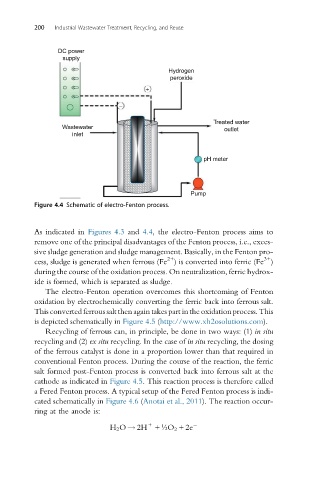
Figure 4.4 Schematic of electro-Fenton process.
As indicated in Figures 4.3 and 4.4, the electro-Fenton process aims to
remove one of the principal disadvantages of the Fenton process, i.e., exces-
sive sludge generation and sludge management. Basically, in the Fenton pro-
3+
2+
cess, sludge is generated when ferrous (Fe ) is converted into ferric (Fe )
during the course of the oxidation process. On neutralization, ferric hydrox-
ide is formed, which is separated as sludge.
The electro-Fenton operation overcomes this shortcoming of Fenton
oxidation by electrochemically converting the ferric back into ferrous salt.
This converted ferrous salt then again takes part in the oxidation process. This
is depicted schematically in Figure 4.5 (http://www.xh2osolutions.com).
Recycling of ferrous can, in principle, be done in two ways: (1) in situ
recycling and (2) ex situ recycling. In the case of in situ recycling, the dosing
of the ferrous catalyst is done in a proportion lower than that required in
conventional Fenton process. During the course of the reaction, the ferric
salt formed post-Fenton process is converted back into ferrous salt at the
cathode as indicated in Figure 4.5. This reaction process is therefore called
a Fered Fenton process. A typical setup of the Fered Fenton process is indi-
cated schematically in Figure 4.6 (Anotai et al., 2011). The reaction occur-
ring at the anode is:
+
H 2 O ! 2H + ½O 2 +2e