
Page 238 - Innovations in Intelligent Machines
P. 238
Toward Robot Perception through Omnidirectional Vision 231
Proof: we want to show that the vertical view angles are equal at corre-
sponding image points, φ 2 (t 2 /F 2 )= φ(t/F) which, from Eq. (2), is the same as
comparing the corresponding derivatives F (t 2 )= F (t) and is demonstrated
2
using the definition of the derivative:
F 2 (τ 2 ) − F 2 (t 2 ) F 2 (ατ) − F 2 (αt) αF (τ) − αF (t)
F (t 2 ) = lim = lim = lim = F (t)
2
τ 2 →t 2 τ 2 − t 2 τ→t ατ − αt τ→t ατ − αt
Simply put, the scaling of the system geometry does not change the local
slope at mirror points defined by fixed image points. In particular, the mirror
slope at the mirror rim does not change and therefore the vertical view angle
of the system does not change.
Notice that despite the vertical view angle remaining constant the observed
3D region actually changes but usually in a negligible manner. As an example,
if the system sees an object 1 metre tall and the mirror rim is raised 5 cm due
to a scaling, then only those 5 cm become visible on top of the object.
Standard mirror profiles are parametric functions and hence implicitly
define the design parameters. Our goal is to specify a large vertical field of
view, φ given the limited field of view of the lens, θ. In the following we detail
the designs of cameras based on spherical and hyperbolic mirrors, which are
the most common standard mirror profiles.
Cameras based on spherical and hyperbolic mirrors, respectively, are
described by the mirror profile functions:
a
2
2
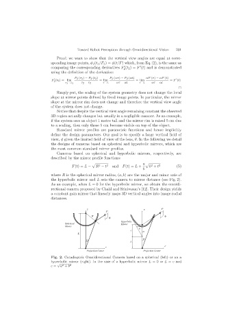
F(t)= L − R − t 2 and F(t)= L + b + t 2 (5)
b
where R is the spherical mirror radius, (a, b) are the major and minor axis of
the hyperbolic mirror and L sets the camera to mirror distance (see Fig. 2).
As an example, when L = 0 for the hyperbolic mirror, we obtain the omnidi-
rectional camera proposed by Chahl and Srinivasan’s [12]. Their design yields
a constant gain mirror that linearly maps 3D vertical angles into image radial
distances.
Fig. 2. Catadioptric Omnidirectional Camera based on a spherical (left) or an a
hyperbolic mirror (right). In the case of a hyperbolic mirror L =0 or L = c and
√
c = a + b 2
2