
Page 240 - Innovations in Intelligent Machines
P. 240
Toward Robot Perception through Omnidirectional Vision 233
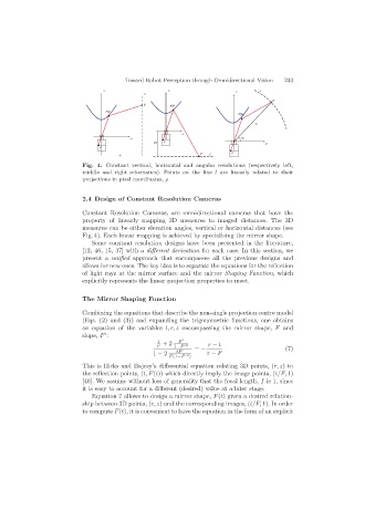
Fig. 4. Constant vertical, horizontal and angular resolutions (respectively left,
middle and right schematics). Points on the line l are linearly related to their
projections in pixel coordinates, ρ
2.4 Design of Constant Resolution Cameras
Constant Resolution Cameras, are omnidirectional cameras that have the
property of linearly mapping 3D measures to imaged distances. The 3D
measures can be either elevation angles, vertical or horizontal distances (see
Fig. 4). Each linear mapping is achieved by specializing the mirror shape.
Some constant resolution designs have been presented in the literature,
[12, 46, 15, 37] with a different derivation for each case. In this section, we
present a unified approach that encompasses all the previous designs and
allows for new ones. The key idea is to separate the equations for the reflection
of light rays at the mirror surface and the mirror Shaping Function,which
explicitly represents the linear projection properties to meet.
The Mirror Shaping Function
Combining the equations that describe the non-single projection centre model
(Eqs. (2) and (3)) and expanding the trigonometric functions, one obtains
an equation of the variables t, r, z encompassing the mirror shape, F and
slope, F :
t F
F +2 1−F 2 r − t
= − (7)
1 − 2 tF z − F
F (1−F 2 )
This is Hicks and Bajcsy’s differential equation relating 3D points, (r, z)to
the reflection points, (t, F(t)) which directly imply the image points, (t/F, 1)
[46]. We assume without loss of generality that the focal length, f is 1, since
it is easy to account for a different (desired) value at a later stage.
Equation 7 allows to design a mirror shape, F(t) given a desired relation-
ship between 3D points, (r, z) and the corresponding images, (t/F, 1). In order
to compute F(t), it is convenient to have the equation in the form of an explicit