
Page 242 - Innovations in Intelligent Machines
P. 242
Toward Robot Perception through Omnidirectional Vision 235
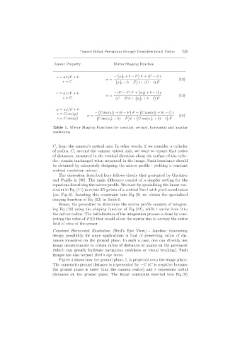
Linear Property Mirror Shaping Function
t
z = a.t/F + b − a F + b − F F +(C − t) t (12)
r = C α = a t + b − F t +(C − t) F
F
t
r = a.t/F + b α = − (C − F) F + a F + b − t t (13)
z = C (C − F) t + a t + b − t F
F
ϕ = a.t/F + b
t t
r = C.cos(ϕ) − C sin(a F + b) − F F + C cos(a F + b) − t t
α = (14)
z = C.sin(ϕ) C sin(a t + b) − F t + C cos(a t + b) − t F
F F
Table 1. Mirror Shaping Functions for constant vertical, horizontal and angular
resolutions
C, from the camera’s optical axis. In other words, if we consider a cylinder
of radius, C, around the camera optical axis, we want to ensure that ratios
of distances, measured in the vertical direction along the surface of the cylin-
der, remain unchanged when measured in the image. Such invariance should
be obtained by adequately designing the mirror profile - yielding a constant
vertical resolution mirror.
The derivation described here follows closely that presented by Gaechter
and Pajdla in [30]. The main difference consist of a simpler setting for the
equations describing the mirror profile. We start by specialising the linear con-
straint in Eq. (11) to relate 3D points of a vertical line l with pixel coordinates
(see Fig. 4). Inserting this constraint into Eq. (9) we obtain the specialised
shaping function of Eq. (12) in Table 1.
Hence, the procedure to determine the mirror profile consists of integrat-
ing Eq. (10) using the shaping function of Eq. (12), while t varies from 0 to
the mirror radius. The initialization of the integration process is done by com-
puting the value of F(0) that would allow the mirror rim to occupy the entire
field of view of the sensor.
Constant Horizontal Resolution (Bird’s Eye View) - Another interesting
design possibility for some applications is that of preserving ratios of dis-
tances measured on the ground plane. In such a case, one can directly use
image measurements to obtain ratios of distances or angles on the pavement
(which can greatly facilitate navigation problems or visual tracking). Such
images are also termed Bird’s eye views.
Figure 4 shows how the ground plane, l, is projected onto the image plane.
The camera-to-ground distance is represented by −C (C is negative because
the ground plane is lower than the camera centre) and r represents radial
distances on the ground plane. The linear constraint inserted into Eq. (9)