
Page 239 - Innovations in Intelligent Machines
P. 239
232 J. Gaspar et al.
Chahl and Srinivasan’s design does not have the single projection centre
property, which is obtained placing the camera at one hyperboloid focus,
√
2
2
i.e. L = a + b , as Baker and Nayar show in [1] (see Fig. 2 (right). In
both designs the system is described just by the two hyperboloid parameters,
a and b.
In order to design the spherical and hyperbolic mirrors, we start by fixing
the focal length of the camera, which directly determines the view field θ.
Then the maximum vertical view field of the system, φ, is imposed with the
reflection law Eq. (2). This gives the slope of the mirror profile at the mirror
rim, F . Stating, without loss of generality, that the mirror rim has unitary
radius (i.e. (1,F(1)) is a mirror point), we obtain the following non-linear
system of equations:
F(1) = 1/ tan θ
. (6)
F (1) = tan (φ − θ) /2
The mirror profile parameters, (L, R)or(a, b), are embedded in F(t), and are
therefore found solving the system of equations.
Since there are minimal focusing distances, D min which depend on the
particular lens, we have to guarantee that F(0) ≥ D min . We do this apply-
ing the scaling property (Eq. (4)). Given the scale factor k = D min /F(0)
the scaling of the spherical and hyperbolic mirrors is applied respectively as
(R, L) ← (k.R, k.L) and (a, b) ← (k.a, k.b). If the mirror is still too small to
be manufactured then an additional scaling up may be applied. The camera
self-occlusion becomes progressively less important when scaling up.
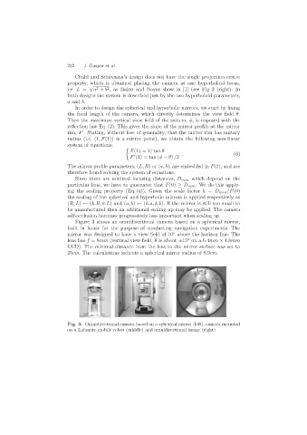
Figure 3 shows an omnidirectional camera based on a spherical mirror,
built in house for the purpose of conducting navigation experiments. The
o
mirror was designed to have a view field of 10 above the horizon line. The
o
lens has f =8mm (vertical view field, θ is about ±15 on a 6.4mm × 4.8mm
CCD). The minimal distance from the lens to the mirror surface was set to
25cm. The calculations indicate a spherical mirror radius of 8.9cm.
Fig. 3. Omnidirectional camera based on a spherical mirror (left), camera mounted
on a Labmate mobile robot (middle) and omnidirectional image (right)