
Page 244 - Innovations in Intelligent Machines
P. 244
Toward Robot Perception through Omnidirectional Vision 237
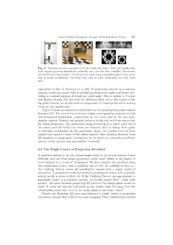
Fig. 5. Svavisca camera equipped with the combined mirror (left) and world scene
with regular patterns distributed vertically and over the floor (middle). Panoramic
and bird’s eye views (right). The bird’s eye views have a transformation from carte-
sian to polar coordinates. The bird’s eye view at right originated from the fovea
area
equivalent to that of Gaechter et al [30]. Of particular interest is a constant
angular resolution sensor, that is an implementation of a spherical sensor pro-
viding a constant number of pixels per solid angle. This is similar to Conroy
and Moore’s design [15], but with the difference that, due to the nature of the
log-polar camera, we do not need to compensate for lesser pixels when moving
closer to the camera axis.
Figure 5 shows an omnidirectional based on the prototype log-polar camera
Svavisca [55]. The mirror is a combined design, encompassing constant vertical
and horizontal resolutions, respectively, in the outer and in the two inner
annular regions. Vertical and ground patterns in the real world are use to test
for linear properties. The panoramic image results from a direct read out of
the sensor and the bird’s eye views are obtained after a change from polar
to cartesian coordinates. In the panoramic image, the vertical sizes of black
squares are equal to those of the white squares, thus showing linearity from
3D measures to image pixel coordinates. In the bird’s eye views the rectilinear
pattern of the ground was successfully recovered.
2.5 The Single Centre of Projection Revisited
A question related to the use of non-single centre of projection sensors is how
different they are from single projection centre ones? What is the degree of
error induced by a locus of viewpoints? We have studied this problem using
the catadioptric sensor with a spherical mirror [33]. As outlined in Sect. 2.1,
the Unifying Theory covers all catadioptric sensors with a single centre of
projection. A projection model governing a catadioptric sensor with a generic
mirror profile is given in Sect. 2.2. If the Unifying Theory can approximate a
non-single centre of projection camera, one would expect that - using both
models - the error between projecting 3D points to the image plane would be
small. It turns out that for real-world points further than 2m away from the
catadioptric sensor the error in the image plane is less than 1pixel.
Derrin and Konolige [23] also approximated a single centre of projection
but used a concept they termed iso-angle mapping. They constructed a virtual