
Page 13 - Solutions Manual to accompany Electric Machinery Fundamentals
P. 13
R 2 R 3 18.0 51.0 0.00235 Wb 0.00062 Wb
right TOT 18.0 51.0 95.5
2 R 3 R R 4
The flux density in the legs can be determined from the equation BA:
0.00148 Wb
B left 0.329 T
left
A 0.09 m 0.05 m
0.00086 Wb
B center 0.115 T
center
A 0.15 m 0.05 m
0.00062 Wb
B left 0.138 T
right
A 0.09 cm 0.05 cm
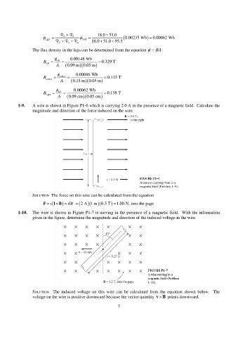
1-9. A wire is shown in Figure P1-6 which is carrying 2.0 A in the presence of a magnetic field. Calculate the
magnitude and direction of the force induced on the wire.
SOLUTION The force on this wire can be calculated from the equation
F i l B ilB 2 A 1 m 0.5 T 1.00 N, into the page
1-10. The wire is shown in Figure P1-7 is moving in the presence of a magnetic field. With the information
given in the figure, determine the magnitude and direction of the induced voltage in the wire.
SOLUTION The induced voltage on this wire can be calculated from the equation shown below. The
voltage on the wire is positive downward because the vector quantity v B points downward.
7