Page 9 - Solutions Manual to accompany Electric Machinery Fundamentals
P. 9

      0.005 Wb
                       B                       0.67 T
                           A         0.15 m    0.05 m

                 The flux density on the right side of the core is
                                 0.005 Wb
                       B                       2.0 T
                           A         0.05 m    0.05 m

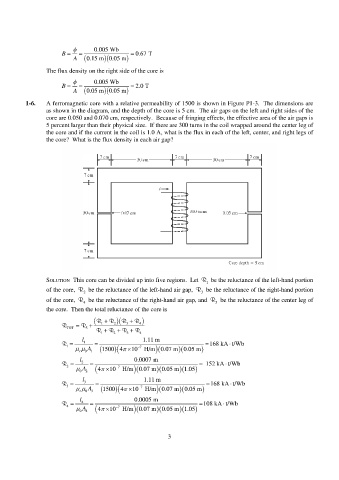
          1-6.   A ferromagnetic core with a relative permeability of 1500 is shown in Figure P1-3.  The dimensions are
                 as shown in the diagram, and the depth of the core is 5 cm.  The air gaps on the left and right sides of the
                 core are 0.050 and 0.070 cm, respectively.  Because of fringing effects, the effective area of the air gaps is
                 5 percent larger than their physical size.  If there are 300 turns in the coil wrapped around the center leg of
                 the core and if the current in the coil is 1.0 A, what is the flux in each of the left, center, and right legs of
                 the core?  What is the flux density in each air gap?


                 SOLUTION  This core can be divided up into five regions.  Let  R 1   be the reluctance of the left-hand portion
                 of the core,  R 2   be the reluctance of the left-hand air gap,  R  be the reluctance of the right-hand portion
                                                                        3
                 of the core,  R 4   be the reluctance of the right-hand air gap, and  R 5   be the reluctance of the center leg of
                 the core.  Then the total reluctance of the core is

                                  R     R   R  R  
                             R   R  1  2   3    4
                        TOT    5       R   R   R  R
                                    1    2    3   4
                              l                    1.11 m
                                                                                  
                       R 1    1                                          168 kA t/Wb
                              A 1   0  1500 4  10  7      H/m  0.07 m    0.05 m
                                           r
                             l                  0.0007 m
                                                                                
                       R 2    2                                        152 kA t/Wb
                                                                 
                             0 A 2    10  7   4     H/m  0.07 m    0.05 m 1.05 
                              l                    1.11 m
                                                                                  
                       R 3    3                                          168 kA t/Wb
                              A 3   0  1500 4  10  7      H/m 0.07 m     0.05 m
                                           r
                             l                  0.0005 m
                                                                               
                       R 4    4                                        108 kA t/Wb
                                                                 
                             0 A 4    10  7  4     H/m  0.07 m    0.05 m 1.05 
                                                            3
   4   5   6   7   8   9   10   11   12   13   14