
Page 12 - Solutions Manual to accompany Electric Machinery Fundamentals
P. 12
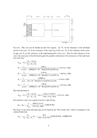
SOLUTION This core can be divided up into four regions. Let R 1 be the reluctance of the left-hand
portion of the core, R 2 be the reluctance of the center leg of the core, R 3 be the reluctance of the center
air gap, and R 4 be the reluctance of the right-hand portion of the core. Then the total reluctance of the
core is the reluctance of the left-hand leg plot the parallel combination of the reluctances of the right-hand
and center legs:
R R R
R R 2 3 4
TOT 1
2 R 3 R R 4
l 1.08 m
R 1 1 95.5 kA t/Wb
A 1 0 2000 4 10 7 H/m 0.09 m 0.05 m
r
l 0.34 m
R 2 2 18.0 kA t/Wb
A 2 0 2000 4 10 7 H/m 0.15 m 0.05 m
r
l 0.0005 m
R 3 3 51.0 kA t/Wb
0 A 3 10 7 4 H/m0.15 m0.05 m 1.04
l 1.08 m
R 4 4 95.5 kA t/Wb
A 4 0 2000 4 10 7 H/m 0.09 m 0.05 m
r
The total reluctance is
R 18.0 51.0 95.5 R R
R R 2 3 4 95.5 135.5 kA t/Wb
TOT 1 R R R 18.0 51.0 95.0
2 3 4
The total flux in the core is equal to the flux in the left leg:
F 100 t 2.0 A
0.00148 Wb
left
TOT
R TOT 135.5 kA t/Wb
The fluxes in the center and right legs can be found by the “flux divider rule”, which is analogous to the
current divider rule.
center R 4 TOT 95.5 0.00148 Wb 0.00086 Wb
2 R 3 R R 4 18.0 51.0 95.5
6