
Page 14 - Solutions Manual to accompany Electric Machinery Fundamentals
P. 14
e vB l vBl cos 45 10 m/s 0.2 T 0.25 m cos 45 0.354 V, positive down
ind
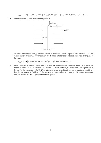
1-11. Repeat Problem 1-10 for the wire in Figure P1-8.
SOLUTION The induced voltage on this wire can be calculated from the equation shown below. The total
voltage is zero, because the vector quantity v B points into the page, while the wire runs in the plane of
the page.
e
vB vBl cos 90 1 m/s 0.5 T 0.5 m cos 90 0 V
l
ind
1-12. The core shown in Figure P1-4 is made of a steel whose magnetization curve is shown in Figure P1-9.
Repeat Problem 1-7, but this time do not assume a constant value of µ . How much flux is produced in
r
the core by the currents specified? What is the relative permeability of this core under these conditions?
Was the assumption in Problem 1-7 that the relative permeability was equal to 1200 a good assumption
for these conditions? Is it a good assumption in general?
8