
Page 75 - Solutions Manual to accompany Electric Machinery Fundamentals
P. 75
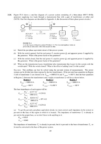
2-24. Figure P2-4 shows a one-line diagram of a power system consisting of a three-phase 480-V 60-Hz
generator supplying two loads through a transmission line with a pair of transformers at either end
(NOTE: One-line diagrams are described in Appendix A, the discussion of three-phase power circuits.)
(a) Sketch the per-phase equivalent circuit of this power system.
(b) With the switch opened, find the real power P, reactive power Q, and apparent power S supplied by
the generator. What is the power factor of the generator?
(c) With the switch closed, find the real power P, reactive power Q, and apparent power S supplied by
the generator. What is the power factor of the generator?
(d) What are the transmission losses (transformer plus transmission line losses) in this system with the
switch open? With the switch closed? What is the effect of adding Load 2 to the system?
SOLUTION This problem can best be solved using the per-unit system of measurements. The power
system can be divided into three regions by the two transformers. If the per-unit base quantities in Region
1 (left of transformer 1) are chosen to be S base1 = 1000 kVA and V , L base1 = 480 V, then the base quantities
in Regions 2 (between the transformers) and 3 (right or transformer 2) will be as shown below.
Region 1 Region 2 Region 3
S base1 = 1000 kVA S base2 = 1000 kVA S base3 = 1000 kVA
V , L base2 = 480 V V , L base2 = 14,400 V V , L base3 = 480 V
The base impedances of each region will be:
3V 2 3 277 V 2
Z 1 0.238
base1
S base1 1000 kVA
3V 2 3 8314 V 2
Z 2 207.4
base2
S base2 1000 kVA
3V 2 3 277 V 2
Z 3 0.238
base3
S base3 1000 kVA
(a) To get the per-unit, per-phase equivalent circuit, we must convert each impedance in the system to
per-unit on the base of the region in which it is located. The impedance of transformer T 1 is already in
per-unit to the proper base, so we don’t have to do anything to it:
R , 1 pu . 0 010
X . 0 040
, 1 pu
The impedance of transformer T 2 is already in per-unit, but it is per-unit to the base of transformer T 2 , so
it must be converted to the base of the power system.
69