
Page 76 - Solutions Manual to accompany Electric Machinery Fundamentals
P. 76
2
V S
Z
( , , ) pu on base 2 ( , , ) pu on base 1 base 1 V 2 base 2 base 2 S (2-60)
R
X
RX
Z
base 1
2
8314 V 1000 kVA
R 2,pu 0.020 8314 V 2 500 kVA 0.040
2
8314 V 1000 kVA
X 2,pu 0.085 8314 V 2 500 kVA 0.170
The per-unit impedance of the transmission line is
Z 1.5 j 10
Z line 0.00723 j 0.0482
line,pu
Z 207.4
base2
The per-unit impedance of Load 1 is
Z 0.45 36.87
Z load1 1.513 j 1.134
load1,pu
Z base3 0.238
The per-unit impedance of Load 2 is
Z j 0.8
Z load2,pu Z load2 0.238 j 3.36
base3
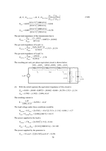
The resulting per-unit, per-phase equivalent circuit is shown below:
0.010 j0.040 0.00723 j0.0482 0.040 j0.170
T Line T
1 2
1.513
10° + - L L
j1.134 1 2
-j3.36
(b) With the switch opened, the equivalent impedance of this circuit is
Z 0.010 j 0.040 0.00723 j 0.0482 0.040 j 0.170 1.513 j 1.134
EQ
Z EQ 1.5702 j 1.3922 2.099 41.6
The resulting current is
10
I 0.4765 41.6
2.099 41.6
The load voltage under these conditions would be
V Z I 0.4765 41.6 1.513 j 1.134 0.901 4.7
Load,pu Load
V Load V Load,pu base3 0.901 480 V 432 V
V
The power supplied to the load is
2
P Load,pu I R Load 0.4765 1.513 2 0.344
P Load P Load,pu S base 0.344 1000 kVA 344 kW
The power supplied by the generator is
P VI cos 0.4765 cos41.6 0.356
1
G ,pu
70