
Page 165 - Instrumentation Reference Book 3E
P. 165
Non-absolute gauges 149
through M. when the pressure is low. A rise in may be passed through it. Since the semicon-
pressure causes an increase of heat loss and a fall ductor has a much greater temperature coefficient
in temperature of the wire. If the power input is of resistance than a metal, a greater sensitivity
kept constant, the wire temperature falls, causing is obtained. Furthermore, on account of its small
a fall of resistance which produces a current size it requires less power, allowing the use of
through M, which is calibrated to read pressure batteries, and it responds more rapidly to sudden
of dry air. Alternatively, the fall in wire tempera- changes of pressure.
ture may be opposed by increasing the input
voltage so that the wire temperature remains con- 10.3.2 Ionization gauges
stant. The input voltage then depends on the
pressure, and the meter measuring the voltage These gauges measure the pressure of gases and
can be scaled to read pressure. The constant bal- vapors over the range IO3 Pa to lo-* Pa by mak-
ance of the bridge is maintained by a simple ing use of the current carried by ions formed in
electronic circuit. This arrangement is effective the gas by the impact of electrons. In the cold-
in extending the high pressure sensitivity of the cathode gauges, the electrons are released from
gauge to IO4 Pa or higher, since the wire tempera- the cathode by the impact of ions, while in the
ture is maintained at this end of the pressure hot-cathode gauges the electrons are emitted by a
range. heated filament.
10.3.1.3 The thermistor gauge 10.3.2.1 The discharge-tube gauge
This gauge ciosely resembles the Pirani gauge in Construction This is the simplest of the cold-
its construction except that a small bead of semi- cathode ionization gauges and operates over the
conducting material takes the place of the metal range from 103Pa to 10-8Pa. The gauge head
wire as the sensitive element. The thermistor bead shown in Figure 10.7 consists of a glass tube
is made of a mixture of metallic oxides, about about 15 cm long and 1 cm in diameter, connected
0.2mm in diameter. It is mounted on two plat- to the vacuum apparatus. A flat or cylindrical
inum wires 0.02 mm in diameter, so that a current metal electrode attached to a gladmetal seal is
mounted at each end. Aluminum is preferable as
it does not readily disintegrate to form metal
films on the gauge walls during use. A stable
power supply with an output of 2.0kV at
2.0 mA is connected across the electrodes, in ser-
ies with a resistor R of about 2MQ to limit the
current, and a 1 mA meter M scaled to read the
pressure.
-*
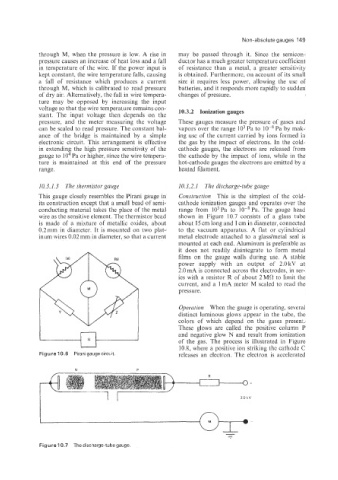
Operation When the gauge is operating, several
distinct luminous glows appear in the tube, the
colors of which depend on the gases present.
These glows are called the positive column P
and negative glow N and result from ionization
10.8, where a positive ion striking the cathode C
Figure 1 0.6 Pirani gauge circuit of the gas. The process is illustrated in Figure
releases an electron. The electron is accelerated
N P
2.0 4v
-
Figure 10.7 The discharge-tube gauge.