
Page 164 - Instrumentation Reference Book 3E
P. 164
148 Measurement of vacuum
encountered by the mercury vapor stream are Operation A stabilized electrical supply S is con-
carried along with it, and are removed from the nected to the hot wire, and adjusted to bring it to
bulb. producing a lowering of the pressure there. the required temperature. The resistance R con-
The effect is greater for large molecules since they nected in series with the millivoltmeter M is used
provide large targets for the mercury vapor to set the zero of the instrument. A rise in the
stream. The error may be reduced by reducing pressure increases the heat loss from the wire, caus-
the mercury vapor flow. by cooling the mercury ing a fall of temperature. This results in a reduction
pool at A artificially, or by reducing the diameter of thermocouple output registered by M, which is
d of the connecting tube. In the latter case the scaled to read pressure of dry air.
response time of the gauge to pressure changes
will be lengthened. 10.3.1.2 The Pirani gauge (Pirani 1906)
Approximate errors for a gauge in which
d = 1 cm, and the mercury temperature is 300 K Construction An electrically heated platinum or
are -4 percent for helium, -25 percent for tungsten wire, operating at a temperature of 320 K,
nitrogen, and -40 percent for xenon. is mounted along the axis of a glass or metal tube,
However, the McLeod gauge, although popu- which is connected to the vacuum apparatus.
lar in the past. is less used nowadays due to the Changes in the pressure cause temperature
difficulty of its operation, its delicate structure changes in the wire, which are followed by using
and size, and its hazardous nature (it contains the corresponding changes in its electrical resis-
mercury). tance. The wire temperature may also be affected
by variations of room temperature and these are
compensated by use of an identical dummy gauge
10.3 Non-absolute gauges head sealed off at a low pressure. The gauge and
dummy heads are shown in Figures 10.4 and 10.5.
10.3.1 Thermal conductivity gauges
For reasons of economy, the dummy head is often
replaced by a bobbin of wire having the same
Function These gauges measure the pressure of resistance and temperature coefficient of resistance.
gases and vapors from 1OOOPa to lo-' Pa by mounted close to the gauge head.
making use of the changes in thermal conductivity
which take place over this range. Separate cali-
bration against an absolute gauge is required for Operation The gauge and dummy heads form
each gas. Since the sensitive element used is an adjacent arms of a Wheatstone bridge circuit as
electrically heated wire, these gauges are known shown in Figure 10.6. This arrangement also
as hot-wire gauges. compensates for the effects of temperature
changes on the resistance of the leads connecting
the gauge head to the control unit, thereby allow-
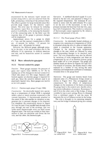
10.3.1.1 Thermocouple gauge (Voege 1906) ing remote indications of pressure. Resistances Y
Construction An electrically heated wire operat- and Z form the other arms of the bridge, Z being
ing at a temperature of about 320K is mounted variable for use in zero setting. Power is obtained
inside a glass or metal envelope connected to the from a stabilized supply S, and the meter M
vacuum apparatus. A thermocouple attached to measures the out-of-balance current in the bridge.
the center of the wire enables its variation in tem- The wire is brought to its operating tempera-
perature due to pressure changes to be observed. ture, and the bridge is balanced giving zero current
For simplicity the construction shown in Figure
10.3 may be used. Four parallel lead-through wires
pass through one end of the envelope, and two
noble metal thermocouple wires are fixed across
diagonal pairs. The wires are welded at their inter-
section so that one dissimilar pair forms the hot
wire, and the other, the thermocouple.
u
Figure 10.3 The thermocouple gauge. Head gauge head. Dummy dummy head