
Page 166 - Instrumentation Reference Book 3E
P. 166
150 Measurement of vacuum
towards the anode, and after travelling some dis- them is a wire anode ring A. Attached to the out-
tance encounters a gas molecule and produces the side of the envelope is a permanent-magnet assem-
ionization which forms the negative glow. Ions bly which produces a transverse magnetic flux
from the negative glow are attracted to the cath- density B of about 0.03T. This greatly increases
ode where further electrons are emitted. This pro- the electron path length and enables a glow dis-
cess, though continuous when established, charge to be maintained at low pressures. An alter-
requires some initial ions to start it. These may native construction, of greater sensitivity, due to
be formed by traces of radioactivity in the envir- Klemperer (1947), is shown in Figure 10.10. This
onment, though some delay may be experienced uses a non-magnetic cylindrical cathode C about
after switching on. The operating pressure range 30mm in diameter and 50mm long, which may
is determined by the electron path lengths. Above form the gauge envelope, along the axis of which
lo3 Pa the motion of the electrons is impeded by is a stiff wire anode A, 1 mm in diameter. An axial
the large number of gas molecules, while below magnetic flux density B of about 0.03 T is provided
about 10-'Pa the electrons travel the whole by a cylindrical permanent magnet or solenoid.
length of the tube without meeting a gas mol-
ecule, and ionization ceases.
Operation A stable 2.0 kV power supply capable
of supplying 2mA is connected in series with a
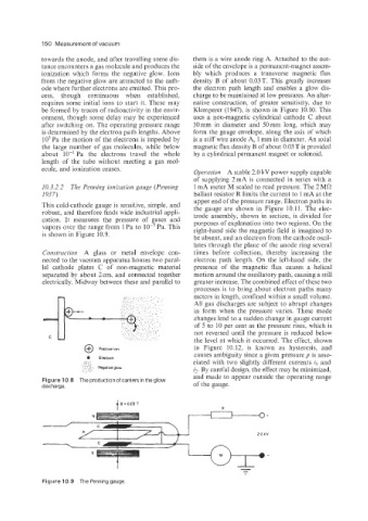
10.3.2.2 The Penning ionization gauge (Penning 1 mA meter M scaled to read pressure. The 2 MR
1937) ballast resistor R limits the current to 1 mA at the
upper end of the pressure range. Electron paths in
This cold-cathode gauge is sensitive, simple, and the gauge are shown in Figure 10.11. The elec-
robust, and therefore finds wide industrial appli- trode assembly, shown in section, is divided for
cation. It measures the pressure of gases and purposes of explanation into two regions. On the
vapors over the range from 1 Pa to Pa. This right-hand side the magnetic field is imagined to
is shown in Figure 10.9.
be absent, and an electron from the cathode oscil-
lates through the plane of the anode ring several
Coizstrziction A glass or metal envelope con- times before collection. thereby increasing the
nected to the vacuum apparatus houses two paral- electron path length. On the left-hand side. the
lel cathode plates C of non-magnetic material presence of the magnetic flux causes a helical
separated by about 2cm, and connected together motion around the oscillatory path, causing a still
electrically. Midway between these and parallel to greater increase. The combined effect of these two
processes is to bring about electron paths many
meters in length, confined within a small volume.
All gas discharges are subject to abrupt changes
in form when the pressure varies. These mode
changes lead to a sudden change in gauge current
of 5 to 10 per cent as the pressure rises, which is
not reversed until the pressure is reduced below
the level at which it occurred. The effect, shown
in Figure 10.12, is known as hysteresis, and
@ Positive ion
causes ambiguity since a given pressure p is asso-
Electron
..:,: . .. . ciated with two slightly different currents il and
. . ..
. . . ....
'. .,.:: . Negative glow
'.. :::: iz. By careful design, the effect may be minimized,
and made to appear outside the operating range
FigurelO.8 The productionofcarrier sin theglow
discharge. of the gauge.
t B = 0.03 T
Figure 10.9 The Penninggauge