
Page 187 - Instrumentation Reference Book 3E
P. 187
Principles of optical fiber sensing 171
deployed today may be expected to last for the to the fiber where the measurement process takes
next 20 years with only a minimum degree of place within the optical fiber medium. In the for-
maintenance. Despite this conservation. optical mer case the optical fiber forms the function of
fiber sensors are progressively finding new appli- transmitting the light to and from the sensor
cation areas due to their unique performance head, while in the latter it actively takes part in
advantages. the sensing process where the inherent optical
properties of the fiber are utilized.
In addition, the optical fiber can be either sin-
12.2 Principles of optical fiber gle mode or multimode, the choice depending
se n s i ng largely on the application and the measurement
method being employed. In general, single-mode
12.2.1 Sensor classification fiber is used for intrinsic optical fiber sensors such
Optical fiber sensors basically consist of an op- as interferometric methods, whereas multimode
tical source coupled to an optical fiber transmis- fibers tend to be used in extrinsic sensor systems
sion line that directs the radiation to a sensor and transmit the light to and from the sensor
head as shown in Figure 12.1. The light is then head. However, there are some notable excep-
returned after being modified in some way by the tions to this generalization. such as micro-bend
sensor interaction, via the optical fiber, in either a sensor systems, for example.
reflective or transmission mode, to a photo-detect-
or and subsequent electronic processing system. 12.2.2 Modulation parameters
The signal processing system then detects, demodu-
lates, and analyzes the changes introduced in Fiber optic sensors operate by the modulation of
the optical signal by the sensor head and then an optical carrier signal by some optical mechan-
relates this to a change in the measurand field of ism present in the sensing region that
interest. is itself responsive to the external parametric
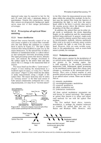
The sensor head can be either a “point sensor,” measurand field. Subsequent signal processing
(Figure 12.2(a)) making the measurement in a of the modulated carrier signal then relates these
localized region in space, or it may be a “distrib- changes to variations in the measurand field of
uted sensor” (Figure 12.2(b)) which has the ability interest. There exist a limited number of such
to make measurements along a length of the possible optical properties that can be modulated
optical fiber. The sensor head may also be either in an optical sensor system. These can be identi-
an “extrinsic sensor’’ to the fiber and consist of fied as:
bulk optical components configured into a sen- (1) intensity modulation
sing mechanism, or it may be an “intrinsic sensor” (2) wavelengtwfrequency modulation
(3) temporal modulation
(4) phase niodulation and
Source Stabilization (5) polarization modulation
Modulation Drive Unit
Optical Fibsr L~nk Measurand
Dnve All these optical modulation parameters are
Fiber Coupler well known in optical metrology. The purpose
in optical fiber sensors is to adopt and extend
Fiber Coupled Sensot Head
optical Source (Ophcal Encoding such methods for use with the optical fiber
Unit) medium.
opto. Elect.
U The first method listed above, intensity
Optical Demodulation Electronic Demodulation/ modulation, is perhaps the simplest technique
indlor Detection Unit Signal Processing Unit
Figure 12.1 Schematic diagram of general optical fiber to consider for optical fiber use (see. e.g..
sensor system operating in the reflective mode. Senior and Murtaza 1989). However, since
“Point”sensor w
Head \\\\
1
Optical fiber link 4 4 4 4 Distributed optical
fiber sensor
Measurand Measurand field sensed
field continuously along fiber
length
(a) (b)
Figure 12.2 Illustration of (a) a”point”optica1 fiber sensor and (b) a distributive optical fiber sensor system