
Page 190 - Instrumentation Reference Book 3E
P. 190
174 Fiber optics in sensor instrumentation
the device actively detects the r.f. modulated or Mach-Zehnder interferometer can also be
photo signal. This type of mixing is particularly used, and the method has been the subject of
useful when considering long path length inter- much early work on optical fiber interferometric
ferometers such as free space ranging devices and sensors. Examples of its use are in the all fiber
Doppler anemometers, used for vibration analy- Mach-Zehnder hydrophone (e.g., Yurek et al.
sis, where optical fibers can be conveniently used 1990), and a Michelson fiber interferometer for
in aspects of the signal processing. quasi-static temperature measurement (Cork
etal. 1983). In this method it is necessary to
provide an arm imbalance L in the fiber inter-
12.3.2 Pseudo-heterodyne interferometry
ferometer in order to facilitate the signal process-
This is an interferometric technique that utilizes ing and to produce the required carrier signal
an optical source, having its emitted radiation for monitoring the optical phase changes induced
frequency modulated. This can either be in the in the sensing interferometer. For an optical
form of a direct frequency modulation of the path imbalance (7fL) in the Michelson inter-
source output wavelength, by modulation of its ferometer, where n is the fiber core refractive
drive injection current, or by use of a fixed fre- index and with a wavelength sawtooth ramp of
quency source but with a Doppler frequency 10GHz frequency modulation (Ax = 0.02nm in
shift introduced by reflection from an oscillat- wavelength) representing a 0.003 percent depth
ing mirror element. The former case has been of modulation, the corresponding change in
treated extensively in optical fiber interferometric output optical phase A@ is given by:
sensors (e.g., Dandridge and Goldberge 1982;
Kersey et al. 1983). A semi-conductor laser diode (12.3)
device has its output frequency modulated by
changes in either its drive current or the device For a 27r change in output phase per wavelength
temperature and experiences a frequency shift of ramp of the laser diode the output interference
about 3 GHz/mA for current changes and about signal from the sensor will transverse one com-
0.25 nm/ "C variation for temperature changes. It plete fringe. It can be seen from the above equal-
is usual to stabilize the device temperature by ity that, for the parameters given, the imbalance
mounting it on a Peltier unit with a thermistor length of the interferometer needs to be about
based feedback control circuit giving tempera- lOmm or greater. Smaller cavity lengths are pos-
ture stabilization down to typically 11100 "C sible but require larger peak wavelength modula-
(about 2.5 pm). When applying a serrodyne cur- tions, and hence heavier current modulations,
rent ramp (a sawtooth ramp with fast fly-back) and in any event the limit will be a few milli-
to the laser diode the output optical frequency meters. A drawback in applying the current modu-
of the device follows a similar modulation and lation is that not only does the process induce the
can be conveniently coupled into a single mode required wavelength modulation, but it also
optical fiber core with typically 10-20% launch induces unwanted intensity modulation across
efficiency. the output waveform (at the same frequency) that
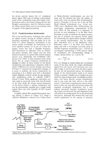
A typical optical fiber pseudo-heterodyne sens- will need to be compensated for in the processing
ing scheme is shown in Figure 12.5 where a electronics. Although this method has seen suc-
reflective Michelson is shown, but a Fabry-Perot cessful application in the sensing of dynamic
AWI
Pia-Tailed imbalance
Sinh LD Wavelength
Mode
Single
Mode Fiber I Fiber Mirror
4 Reflectors
Optical Fiber Sensor:
Michelson interferometer
Photo
Detector Filter 8 fm
Ramp Sine Wave Carrier
Generator output
(Phase Modulated by L)
Figure 12.5 Optical fiber Michelson interferometer illustrating a pseudo-heterodyne modulation scheme using an
unbalanced interferometer (Cork et al. 1983).