
Page 194 - Instrumentation Reference Book 3E
P. 194
178 Fiber optics in sensor instrumentation
Spacer Diaphragm
LED Multi-Mode Optical
Source Fiber Coupler Fiber Link Applied
>
Fabry-Perot Partial
Mirror 4 k-
;- .. LS
-
..
LRi
I I ;- - LRi Circuit Pressure
Circuit
Sensor
+ +
-!
-!
Gri
Control
Head
Circuit i i Gri Control Fabry-Perot
Circuit
(Capacitive) i Dete i Dete
(Capacitive)
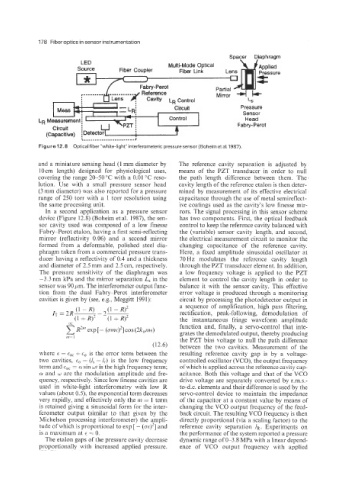
Figure 12.8 Optical fiber "white-light" interferometeric pressure sensor (Boheim et al. 1987).
and a miniature sensing head (1 mm diameter by The reference cavity separation is adjusted by
10 cin length) designed for physiological uses, means of the PZT transducer in order to null
covering the range 20-50 "C with a 0.01 "C reso- the path length difference between them. The
lution. Use with a small pressure sensor head cavity length of the reference etalon is then deter-
(3 mm diameter) was also reported for a pressure mined by measurement of its effective electrical
range of 250 torr with a 1 torr resolution using capacitance through the use of metal semireflect-
the same processing unit. ive coatings used as the cavity's low finesse mir-
In a second application as a pressure sensor rors. The signal processing in this sensor scheme
device (Figure 12.8) (Boheim et al. 1987), the sen- has two components. First, the optical feedback
sor cavity used was composed of a low finesse control to keep the reference cavity balanced with
Fabry-Perot etalon, having a first semi-reflecting the (variable) sensor cavity length, and second,
mirror (reflectivity 0.06) and a second mirror the electrical measurement circuit to monitor the
formed from a deformable, polished steel dia- changing capacitance of the reference cavity.
phragm taken from a commercial pressure trans- Here, a fixed amplitude sinusoidal oscillator at
ducer having a reflectivity of 0.4 and a thickness 70 Hz modulates the reference cavity length
and diameter of 2.5 mm and 2.5 cm, respectively. through the PZT transducer element. In addition,
The pressure sensitivity of the diaphragm was a low frequency voltage is applied to the PZT
-3.3nm kPa and the mirror separation L, in the element to control the cavity length in order to
sensor was 90 pm. The interferometer output func- balance it with the sensor cavity. This effective
tion from the dual Fabry-Perot interferometer error voltage is produced through a monitoring
cavities is given by (see, e.g., Meggitt 1991): circuit by processing the photodetector output in
IT = 2R- (1 - R) - 2- (1 - R)' a sequence of amplification, high pass filtering.
rectification, peak-following, demodulation of
(1 + R)' (1 + R)' the instantaneous fringe waveform amplitude
oc function and, finally, a servo-control that inte-
R~~~~ exp 1- (~IzE)'] COS (2k,n1t)
grates the demodulated output, thereby producing
111=1 the PZT bias voltage to null the path difference
(12.6) between the two cavities. Measurement of the
where E = + E, is the error term between the resulting reference cavity gap is by a voltage-
two cavities, = (I, - &) is the low frequency controlled oscillator (VCO), the output frequency
term and tac = a sin (*it is the high frequency term; of which is applied across the reference cavity cap-
CY and w are the modulation amplitude and fre- acitance. Both this voltage and that of the VCO
quency, respectively. Since low finesse cavities are drive voltage are separately converted by r.m.s.-
used in white-light interferometry with low R to-d.c. elements and their difference is used by the
values (about OS), the exponential term decreases servo-control device to maintain the impedance
very rapidly, and effectively only the ni = 1 term of the capacitor at a constant value by means of
is retained giving a sinusoidal form for the inter- changing the VCO output frequency of the feed-
ferometer output (similar to that given by the back circuit. The resulting VCO frequency is then
Michelson processing interferometer) the ampli- directly proportional (via a scaling factor) to the
tude of which is proportional to exp [ - (a€)'] and reference cavity separation 1~. Experiments on
is a maximum at E = 0. the performance of the system reported a pressure
The etalon gaps of the pressure cavity decrease dynamic range of 0-3.8 MPa with a linear depend-
proportionally with increased applied pressure. ence of VCO output frequency with applied