
Page 197 - Instrumentation Reference Book 3E
P. 197
Interferometric sensing approach 181
[2T r; + k) ] } (1 2.1 6)
.. Here, N is the number of pixel elements per
i moire fringe and y is the pixel distance along
the CCD array. If we choose W(moii-6) =
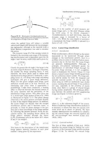
Figure 12.'13 Moire pattern from beating between an N(interferometric), as used previously, then the
dynamic range is increased by a factor of
interferometric fringe pattern and a CCD pixel array structure,
for a large mirror tilt angle (Chen et al. 1990). N(K + U2). While the same degree of resolution
is maintained, the fringe visibility is reduced by a
where the applied force will induce a variable factor of T(K + 1/2).
optical path length shift between the two propagat-
ing eigenmodes, although in the reported work a 12.3.4 Central fringe identification
SoEeil-Babinet compensator was used to simulate
this action. 12.3.4.1 Introduction
The dynamic range R of the sensing system is While interferometry allows changes in the sensor
limited to the maximum scan range of the process- measurand to be monitored through phase
ing interferometer and is dependent upon the tilt changes in the interference pattern, there is a
angle /3 and the array width (Mp) and is given by: problem when it comes to making absolute meas-
urements due to the fact that the cosine fringes
(1 2.14) are generally indistinguishable. Although, in
principle, low-coherent techniques permit the
Clearly the greater the tilt angle /3 the larger is the identification of individual fringes through the
dynamic range R. However, the larger $'becomes, Gaussian fringe envelope, it is not straightfor-
the smaller the fringe sampling factor N and, ward to implement this feature. Figure 12.11(a)
therefore, the fewer pixels used to define each shows a typical output fringe interferogram from
interferometric fringe period h. Ordinarily, a sam- the low coherence sensor system. The fringe pat-
pling factor of >20 along with fringe smoothing tern will be similar for both the temporal and
techniques will give a good fringe definition. spatially scanned systems. It can be seen that
When too few pixels sample each fringe, good when using an LED (or multimode laser diode)
definition would seem to be lost. However, an source, tracking the central fringe of this profile is
interesting case arises when N approaches 2 not easy, especially in the presence of excess
pixeldfringe. Under these conditions, a beating noise, since there is a group of central fringes
effect is observed between the discrete nature of having similar amplitudes. The amplitude differ-
the array elements and the periodicity of the ence between the central and first neighboring
interference fringe pattern. This effect gives rise fringe (see Figure 12.11(b)) is given by:
to a moirk-type fringe pattern (Chen et al. 1990)
as illustrated in Figure 12.13. The phase change (12.17)
observed in the moire pattern correlates directly
to that of the original fringe pattern. In addition,
the moire fringes are sharper than the straight where L, is the coherence length of the source.
interference pattern and it becomes easier, in When considering fringe identification methods it
principle, to track the phase changes in the pat- is necessary to ensure that they can operate with
tern and tso have knowledge of the fringe number noise levels up to about 10 percent. We have
by following the pattern centroid. From the dis- recently demonstrated two methods for identify-
cussion earlier, the sampling factor affects the ing the central fringe: the centroid method and
fringe paitern intensity through the factor the two-wavelength beat method (Chen et al.
<(p/b). Expressing (plb) as the factor KIN? where 1992b, 1993).
K and N are integers:
12.3.4.2 Centroid nzethod
The first of these methods (Chen etal. 1992b)
This leads to the description of the interference identifies the central fringe by finding the center
fringe pattern intensity function at each pixel ofgravity of the Gaussian fringe pattern envelope
number i being given by the expression: (Figure 12.14). To identify the central fringe