
Page 193 - Instrumentation Reference Book 3E
P. 193
Interferometric sensing approach 177
for the intense recent interest in the low coher- Perot cavity sensor element was composed of a
ence method. It should also be pointed out that thin Sic film etalon (Boheim 1986). The refer-
unlike the current-modulated pseudo-heterodyne ence cavity is temperature controlled and its out-
method, the low coherence method can operate, put interference signal is used in a feedback
under suitable conditions, with multimode as well control to stabilize the mean imbalance of the
as single mode optical fibers. The requirement Michelson processing interferometer. The piezo-
here is that the light returned from the optical electric modulator PZTl drives one mirror of the
sensing interferometer satisfies the common Michelson in a serrodyne (sawtooth) waveform
mode condition such that both reflected beams in order to scan a complete output interference
from the two interferometer mirrors follow sinusoidal temporal fringe in the outputs from
exactly the same modal path when transmitted both the cavity elements. By utilizing the tem-
back through the multi-mode optical fiber or, if perature stabilized reference sensor output and
not, then sufficient mode mixing occurs in the by interacting with PZT2, the feedback control
fiber length to evenly distribute the back-reflected circuit compensates for both thermal and vibra-
light into all the fiber modes (Chen et al. 1992a). tion instabilities in the processing interferometer.
One of the first successful practical demon- The sensor element in this work was separated
strations of the capability of the white-light tech- from the fiber sensor lead by an air path since the
nique was reported by Boheim (1985). In this elevated temperature of 1000 "C used was well
system a multimode optical fiber link was used above the survival temperature of the fiber net-
with a Michelson reference interferometer and a work. The collimated output from the fiber sen-
low finesse Fabry-Perot sensor cavity. Further sor lead was reflected back from the remotely
analysis was then given in subsequent publica- placed Sic sensor etalon. The SIC etalon was
tions. and the system was later applied to a high 18 pm thick and deposited on a silicon substrate.
temperature sensor (Boheim and Fritsch 1987) The reflected radiation was relaunched back into
and a pressure sensing device (Boheim etal. the optical fiber and returned through a second
1987). A similar approach using single mode directional coupler to an output photodetector.
fiber techniques has been used by Meggitt Phase movement in the output fringe pattern of
(1991) in a prototype system in physiological the sensor cavity was a direct measure of tem-
applicatioins for temperature and pressure meas- perature of the sensor etalon. Measurements were
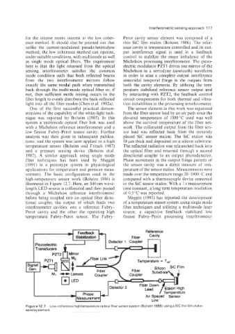
urement. The basic configuration used in the made over the temperature range 20-1000 "C and
high-temperature sensor work (Boheim 1986) is compared with a thermocouple device cemented
illustrated in Figure 12.7. Here, ai? 840nm wave- to the Sic sensor etalon. With a 1 s measurement
length LED source is collimated and then passed time constant, a long term temperature resolution
through a Michelson reference interferometer of 0.5 "C was reported.
before being coupled into an optical fiber direc- Meggitt (1991) has reported the development
tional coupler, the output of which feeds two of a temperature sensor system- using single mode
interferometer cavities: one a reference Fabry fiber techniques and utilizing a multimode laser
Perot cavity and the other the operating high source, a capacitive feedback stabilized low
temperature Fabry-Perot sensor. The Fabry finesse Fabry-Perot processing interferometer
h
h Reference
Feedback
Stabiliition
Temperature = T,,t
Fiber Substrate
Figure 12.7 Low-coherence high temperature optical fiber sensor system (Boheim 1986) using a Sic thin film etalon
sensing element