
Page 198 - Instrumentation Reference Book 3E
P. 198
182 Fiber optics in sensor instrumentation
I"' " ' ' ' 1 ~ ~ ' ' ' "'l""'""l""""'~'~ ' 1
80 260 480 680 880 1080
Pixel number
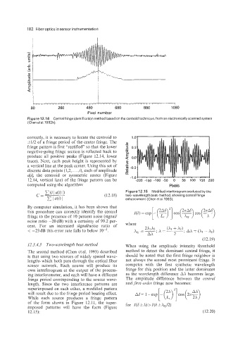
Figure 12.14 Central fringe identification method based on the centroid technique, from an electronically scanned system
(Chen et a1.1992b).
correctly, it is necessary to locate the centroid to
-
&1/2 of a fringe period of the center fringe. The a
fringe pattern is first "rectified" so that the lower U
.- -
s 0.5
negative-going fringe section is reflected back to
E
produce all positive peaks (Figure 12.14, lower a 0.0
trace). Next, each peak height is represented by J
a vertical line at the peak center. Using this set of .-
c
discrete data points (1,2, . . . ,i), each of amplitude - -0.5
d
a[$ the centroid or symmetric center (Figure . . . . . I
12.14, vertical line) of the fringe pattern can be -1.04 - . * . . . 'j ' 50 100 150 200
-200 -150 -100 -50
0
computed using the algorithm: Pixels
Figure 12.15 Modified interferogram produced by the
( 1 2.1 8) two-wavelength beat-method, showing central fringe
enhancement (Chen et al. 1993).
By computer simulation, it has been shown that
this procedure can correctly identify the central
fringe in the presence of 10 percent noise (signall
noise ratio -20dB) with a certainty of 99.2 per-
cent. For an increased signalhoke ratio of
< -23 dB this error rate falls to below
(12.19)
12.3.4.3 Two-wavelength beat method When using the amplitude intensity threshold
The second method (Chen et al. 1993) described method to detect the dominant central fringe, it
is that using two sources of widely spaced wave- should be noted that the first fringe neighbor is
lengths which both pass through the optical fiber not always the second most prominent fringe. It
sensor network. Each source will produce its competes with the first synthetic wavelength
own interferogram at the output of the process- fringe for this position and the latter dominates
ing interferometer, and each will have a different as the wavelength difference AA becomes large.
fringe period corresponding to the source wave- The amplitude difference between the central
length. Since the two interference patterns are and first-order fringe now becomes:
superimposed on each other, a modified pattern
will result due to the fringe period beating effect.
While each source produces a fringe pattern
of the form shown in Figure 12.11, the super- for I(S+A) >I(S&A,,/2)
imposed patterns will have the form (Figure
12.15): (12.20)