
Page 196 - Instrumentation Reference Book 3E
P. 196
180 Fiber oPtics in sensor instrumentation
(N pixels/fringe) associated with the discrete 10
nature of the CCD pixel array given by W
U
3 0.5
= -
$ 00
and ci 1 for N > 10 pixeldfringe -
m
2
m -0.5
(12.10) -
m
a
and v(61 - 62 + 2y,O) is the visibility function - 1 .o
associated with the temporal coherence properties -200-150-100-50 0 50 100 150 200
of the source and is given by (a) Pixels
461 - 62 + 2yP) =
The fringe period will therefore have a spatial
width b equal to:
(1 2.12)
b= ($7) 0
z
where XO is the central wavelength of the source. /
6s
For a CCD array that is composed of M pixel Phase (radian) +
elements each of width p, then the number of (b)
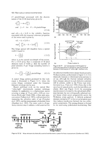
pixel elements N per fringe (sampling factor) is Figure 12.11 (a) Typical output interferogramfor
given by: multimode laser diode or LED source, and (b) structural
features of interferogram in "white-light" interferometry.
($2 the reference interferometer design based around a
N = - = ~ pixeldfringe (12.13) Wollaston prism, as illustrated in Figure 12.12. It is
inherently resistant to vibrational noise and easy to
A typical fringe pattern produced by this tech- set up, although the thermal induced refractive
nique is illustrated in Figure 12.11, where the index changes inherent in such dielectric materials
cosine fringes contained under the Gaussian will be present, unlike in the Fizeau type inter-
intensity envelope can be seen. ferometer (e.g., Chen et al. 1991) where, due to the
Recent published work on the optical fiber use of an air spaced cavity, such thermal effects are
"white-light'' electronically scanned technique absent. Here (see Figure 12.12) the processing
includes its application to a displacement sensor interferometer is formed by the optical path differ-
covering a range of 75pm with a 0.02pm reso- ence between the two orthogonally polarized out-
lution (Koch and Ulrich 1990), a fiber optic pres- put beams which occurs progressively across the
sure sensor (Valluet et al. 1987), a refractometer for Wollaston prism aperture. A dichroic polarized
measuring the refractive index of air (Trouchet element oriented at 45" to the two polarization axes
et al. 1992), and the measurement of absolute force then induces interference between the two ortho-
(Danliker etal. 1992). The latter work is of par- gonal components. The sensing element is formed
ticular interest since it utilizes a solid construct for in the intervening polarization-maintaining fiber
Polarizer
LED
Source
llkp
-
I
Polarizer r I Fiber 7 I-
.- -
Lens [
450 to Collimating Imaging
Fiber Axes Lens
Image of Spatial
Fringe Pattern
Figure 12.1 2 Noise resistant electronically scanned interferometric system for force measurement (Danliker et al. 1992).