
Page 188 - Instrumentation Reference Book 3E
P. 188
172 Fiber optics in sensor instrumentation
there are many processes in an optical fiber measurement channel. These components are
network that can also modulate the intensity referred to as:
of the transmitted radiation, e.g., coupler loss (1) common mode modulation
and bend loss, it cannot be used directly with- (2) differential mode modulation
out providing an additional processing tech-
nique that can unambiguously identify the The “common mode” signal is one that has the
intensity changes induced solely by the meas- same noise spectrum for both output channels,
ure and interaction of interest. The most com- the signal and reference channels, and can be
mon method for providing this facility in the eliminated by ratioing of (dividing) the two
intensity modulated sensor is to use a two- signals once they have experienced the same
wavelength referencing technique, e.g., for gas system gain. The “differential mode” output,
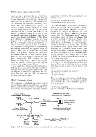
sensing see Bianco and Baldini (1993). Here, on the other hand, will reflect the changes that
two different wavelength sources are used have been induced by the sensor head on the
(Figure 12.3) where one, the signal channel, signal output only, with the reference beam
has its wavelength variably absorbed by the ideally being unaffected by the sensor changes.
sensor interaction and the second channel acts Therefore, the division process that removes
as a reference wavelength that is unaffected by the common mode signal effects will leave
the sensing interaction and against which the unaltered the differential mode effects. The
sensing signal can be normalized for system residual noise output from this processing stage
losses. It is, however, necessary to ensure that will reflect the degree to which the noise spec-
the optical fiber link to and from the sensor trum is common to both signals and the degree
head has the same spectral response to both to which the reference signal is unperturbed by
beam wavelengths. This requires the two the sensing mechanism.
beams to have closely spaced wavelengths; As mentioned earlier, sensor systems will each
these are usually produced from the spectral have their own related operating performance
division of a single source element. factors. These can be identified as those factors
In principle, the other listed optical modulation that help define a measurement point. and
techniques are immune to intensity modulation include:
changes in the fiber link, provided that some form
of temporal modulation is applied to the radi- (1) resolution, responsivity, sensitivity
ation and that the link does not introduce (2) accuracy
addition modulation effects. (3) reproducibility
These are distinct performance related factors
12.2.3 Performance criteria and not merely different ways of expressing the
same quantity. Two other important perform-
The processing of signal and noise components of ance criteria are:
the modulated signals returned from an optical
fiber sensor are similar to those commonly found (4) dynamic range and
in electronic sensor systems utilizing a reference (5) low cross-sensitivity to other parameters
Source 1 @ hi Intensity of A, Variably
-
(Measurement Wavelength) Attenuated with Measurand
+
Sensor Element
Absorbing to hl
Only
S Intensity of h2 Unaffected
(refer by Measurand Changes
Photo- Photo- Detection of Differential Absorption
Detector 1 Detector 2 Between XI and h2
Signal Signal
Channel Channel
Figure 12.3 Typical configuration for a two-wavelength intensity modulated optical fiber sensor system.