
Page 245 - Instrumentation Reference Book 3E
P. 245
Fieldbus 229
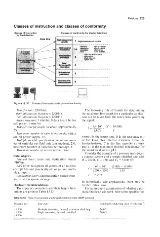
Classes of instruction and classes of conformity
I
Figure 13.37 Classes of instruction and classes of conformity.
Transfer rate: 1200 bitls. The following rule of thumb for determining
0 bit information frequency: 2200 Hz. the maximum line length for a particular applica-
1 bit injormation frequency: 1200 Hz. tion can be taken from the restrictions governing
Signalstructure: 1 start bit, 8 data bits, 1 bit for the signal:
odd parity, 1 stop bit.
65. lo6 (C + 10.000)
Transfer rate for simple vuriables: approximately l=--
US. (RC) C
Maximum number of units in bus mode: with a
central power supply, 15. where I is the length (m), R is the resistance (0)
Multiple variable specification: maximum num- of the load plus internal resistance from the
ber of variables per field unit (one modem), 256; barrierlisolator, C is the line capacity (pF/m),
maximum number of variables per message, 4. and Cf is the maximum internal capacitance for
Maximum number of master systems: two. the smart field units (pF).
Consider the example of a pressure transducer,
Data integrity a control system and a simple shielded pair with
Physical layer: error rate destination circuit R = 250 0, C = 150, and Cf = 5.000 pF:
1/105 bit.
Link layer: recognizes all groups of up to three 65 x lo6 (5.000 + 10.000)
corrupt bits and practically all longer and multi- I= (250 x 150) - 150
ple groups.
Application layer: communication status trans- 1 = 1633m
mitted in a response message.
In intrinsically safe applications, there may be
Hardware recommendations further restrictions.
The types of connection and their length limi- For an in-depth examination of whether a par-
tations are given in Table 13.13. ticular hook-up will work, refer to the specification
Table13.13 Type of connection and length limitations in the HART protocol
Distance (m) Line type Minimum conducting area (AWG/mm')
__ -
<1.500 Multiple two-wire, twisted, common shielding 2410.2
>IS00 Single two-wire, twisted, shielded 2010.5
53.000
. - . . -..