
Page 240 - Instrumentation Reference Book 3E
P. 240
224 Microprocessor-based and intelligent transmitters
Work to develop a single international stand- of operating in the system but also for equipment
ard for fieldbus started in 1985. The intervening from one manufacturer to work together with
period saw the development of a variety of local that from another. This emphasizes the import-
national standards and proprietary industrial ance of establishing an international fieldbus
standards, leading to the present situation where standard but, at present, the cost and functional-
several standards are competing to become the ity benefits associated with an “open” system is
accepted industry standard. In spite of this, field- not being fully realized because of the competing
bus is now having a dramatic effect on the control “open” systems currently available.
industry.
13.10.3 Current digital multiplexing technology
13.10.2 Introduction to the concept of a fieldbus
Fieldbus protocols and systems have been devel-
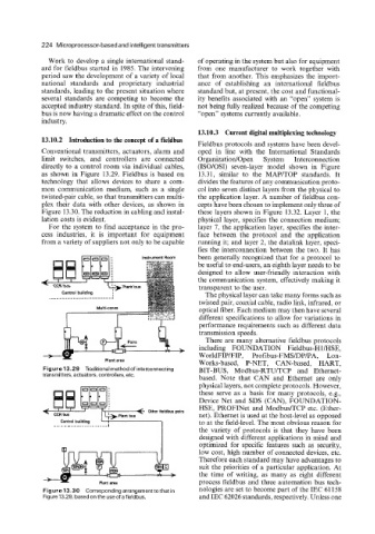
Conventional transmitters, actuators, alarm and oped in line with the International Standards
limit switches, and controllers are connected OrganizatiodOpen System Interconnection
directly to a control room via individual cables, (ISO/OSI) seven-layer model shown in Figure
as shown in Figure 13.29. Fieldbus is based on 13.31, similar to the MAP/TOP standards. It
technology that allows devices to share a com- divides the features of any communication proto-
mon communication medium, such as a single col into seven distinct layers from the physical to
twisted-pair cable, so that transmitters can multi- the application layer. A number of fieldbus con-
plex their data with other devices, as shown in cepts have been chosen to implement only three of
Figure 13.30. The reduction in cabling and instal- these layers shown in Figure 13.32. Layer 1, the
lation costs is evident. physical layer, specifies the connection medium;
For the system to find acceptance in the pro- layer 7, the application layer, specifies the inter-
cess industries, it is important for equipment face between the protocol and the application
from a variety of suppliers not only to be capable running it; and layer 2, the datalink layer, speci-
fies the interconnection between the two. It has
been generally recognized that for a protocol to
be useful to end-users, an eighth layer needs to be
designed to allow user-friendly interaction with
f the communication system, effectively making it
transparent to the user.
The physical layer can take many forms such as
twisted pair, coaxial cable, radio link, infrared, or
optical fiber. Each medium may then have several
different specifications to allow for variations in
performance requirements such as different data
transmission speeds.
There are many alternative fieldbus protocols
including FOUNDATION Fieldbus-HI/HSE,
WorldFIP/FIP, Profibus-FMS/DP/PA, Lon-
Works-based, P-NET, CAN-based, HART,
Figure 13.29 Traditional method of interconnecting BIT-BUS, Modbus-RTUITCP and Ethernet-
transmitters, actuators, controllers, etc. based. Note that CAN and Ethernet are only
physical layers, not complete protocols. However,
these serve as a basis for many protocols, e.g.,
Device Net and SDS (CAN), FOUNDATION-
HSE, PROFINet and ModbudTCP etc. (Ether-
._ net). Ethernet is used at the host-level as opposed
Control building : I to at the field-level. The most obvious reason for
the variety of protocols is that they have been
designed with different applications in mind and
optimized for specific features such as security,
low cost, high number of connected devices, etc.
Therefore each standard may have advantages to
suit the priorities of a particular application. At
the time of writing, as many as eight different
process fieldbus and three automation bus tech-
Figure 13.30 Corresponding arrangement tothat in nologies are set to become part of the IEC 61158
Figure 13.29, based on the use of a fieldbus. and IEC 62026 standards, respectively. Unless one