
Page 237 - Instrumentation Reference Book 3E
P. 237
Other microprocessor-based and intelligent transmitters 221
computes the density, taking into account the The application data which are entered
operating temperature and pressure. include:
For gas density measurements: it is important
to know both the temperature and pressure. The (1) Tag (an eight-character field)
former is measured by a four-wire 1000 platinum (2) Descriptor (a 16-character field)
RTD located in the wall of the chamber, but the (3) Message (a 32-character field)
latter has to be measured by a separate pressure (4) Date
transmitter . (5) Pipe description
y-Way absorption can be used to measure (6) Process description.
the density of moving or flowing liquids, slurries, The digital trim involves:
or solids, and the Thermo Measuretech (Formerly
TN and KAURAU) Model 3660 system (see (1) Reference to the process
References) provides an example of this. In it, (2) Development of the process density calibra-
the y-beam emitted from a source is directed tion curve
through the process pipe towards the detector/ (3) Calibration of the temperature input
electronics. The amount of 7-radiation that passes (4) Calibration of the &2OmA output.
completely through the pipe and its contents
varies inversely with the density of the material
within the pipe. The detector/electronics contains 13.8.2 Microprocessor-based and intelligent
a scintillation counter which, when subjected to liquid level measurement systems
the y-beam, produces light photons which are
amplified through a scintillation sensor. The num- A great many level measurements which are made
ber of pulses from the scintillation sensor is directly for process control purposes are based on the
proporticma to the intensity of the received beam. measurement of hydrostatic pressure. and are
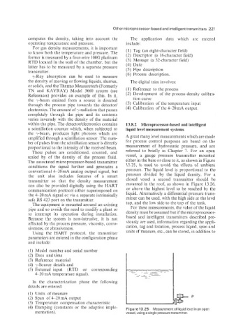
These pulses are conditioned, counted, and referred to briefly in Chapter 7. For an open
scaled by of the density of the process fluid. vessel, a gauge pressure transmitter mounted
The associated microprocessor-based transmitter either in the base or close to it, as shown in Figure
conditions the signal further and generates a 13.25, is used to avoid the effects of ambient
conventional 4-20 mA analog output signal, but pressure. The liquid level is proportional to the
the unit also includes features of a smart pressure divided by the liquid density. For a
transmitter so that the density measurement closed vessel a second transmitter should be
can also be provided digitally using the HART mounted in the roof, as shown in Figure 13.26.
communication protocol either superimposed on or above the highest level to be reached by the
the 4-20 inta signal or via a separate intrinsically liquid. Alternatively a differential pressure trans-
safe RS 4.23 port on the transmitter. mitter can be used, with the high side at the level
The equipment is mounted around an existing tap, and the low side to the top of the tank.
pipe and so avoids the need to modify a plant or For these measurements. the value of the liquid
to interrupt its operation during installation. density must be assumed but if the microprocessor-
Because the system is non-intrusive, it is not based and intelligent transmitters described pre-
affected by the process pressure, viscosity, corro- viously are used, information regarding the appli-
siveness, or abrasiveness. cation, tag and location, process liquid, span and
Using the HART protocol, the transmitter units of measure. etc., can be stored, in addition to
parameters are entered in the configuration phase
and include:
(1) Model number and serial number
(2) Date and time
(3) Reference material
(4) 7-Source details and
(5) External input (RTD or corresponding
4-10 mA temperature signal).
In the characterization phase the following
details are entered:
(1) Units of measure
(2) Span of 420 mA output P
(3) Temperature compensation characteristic
(4) Damping (constants or the adaptive imple- Figure 13.25 Measurement of liquid level in an open
mentation). vessel, using a single pressure transmitter.