
Page 233 - Instrumentation Reference Book 3E
P. 233
Microprocessor-based and intelligent flowmeters 217
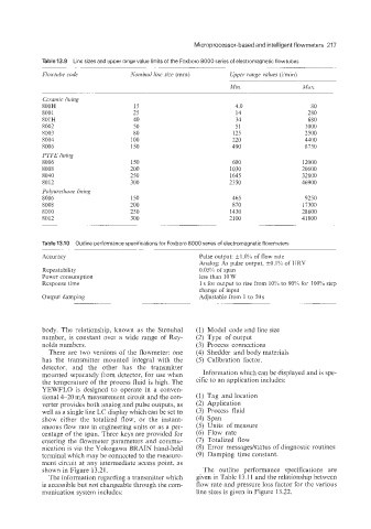
Table139 Line sizes and upper range value limits of the Foxboro 8000 series of electromagnetic flowtubes
-
Flowtube code Nominal line size (mm) Upper range values (Vmin)
Min. Max.
Ceramic lining
800R 15 4.0 80
8001 25 14 280
801R 40 34 680
8002 50 51 1000
8003 80 125 2500
8004 100 220 4400
8006 150 490 8750
PTFE lining
8006 150 600 12000
8008 200 1030 20600
8040 250 1645 32800
8012 300 2350 46900
Polyuretlzane lining
8006 150 465 9250
8008 200 870 17300
8010 250 1430 28600
8012 300 2100 41800
Table 13.10 Outline performance specifications for Foxboro 8000 series of electromagnetic flowmeters
~
Accuracy Pulse output: +1.0% of flow rate
Analog: As pulse output, +0.1% of URV
Repeatability 0.05% of span
Power consumption less than 1OW
Response time 1 s for output to rise from 10% to 90% for 100% step
change of input
Output damping Adjustable from 1 to 50 s
body. The relationship, known as the Strouhal (1) Model code and line size
number, is constant over a wide range of Rey- (2) Type of output
nolds numbers. (3) Process connections
There are two versions of the flowmeter: one (4) Shedder and body materials
has the transmitter mounted integral with the (5) Calibration factor.
detector, and the other has the transmitter
mounted separately from detector, for use when Information which can be displayed and is spe-
the temperature of the process fluid is high. The cific to an application includes:
YEWFLO is designed to operate in a conven-
tional 4-20 mA measurement circuit and the con- (1) Tag and location
verter provides both analog and pulse outputs, as (2) Application
well as a single line LC display which can be set to (3) Process fluid
show either the totalized flow, or the instant- (4) Span
aneous flow rate in engineering units or as a per- (5) Units of measure
centage of the span. Three keys are provided for (6) Flow rate
entering the flowmeter parameters and commu- (7) Totalized flow
nication is via the Yokogawa BRAIN hand-held (8) Error messages/status of diagnostic routines
terminal which may be connected to the measure- (9) Damping time constant.
ment circuit at any intermediate access point, as
shown in Figure 13.21. The outline performance specifications are
The information regarding a transmitter which given in Table 13.1 1 and the relationship between
is accessible but not changeable through the com- flow rate and pressure loss factor for the various
munication system includes: line sizes is given in Figure 13.22.