
Page 232 - Instrumentation Reference Book 3E
P. 232
216 Microprocessor-based and intelligent transmitters
REMOVABLE
COMMUNICATIONS
CABLE
DISPLAY
KEYBOARD
WHEN COVER
EXTENDED)
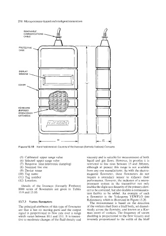
Figure 13.19 Hand-held terminal. Courtesyof the lnvensys (formerly Foxboro) Company.
(5) Calibrated upper range value viscosity and is suitable for measurement of both
(6) Selected upper range value liquid and gas flows. However, in practice it is
(7) Response time (electronic damping) restricted to line sizes between 15 and 300mm,
(8) Nominal line size although at present this range is not available
(9) Device name from any one manufacturer. As with the electro-
(10) Tag name magnetic flowmeter, these flowmeters do not
(11) Tag number require a secondary sensor to enhance their
(12) Location. performance. However, the inclusion of a micro-
processor system in the transmitter not only
Details of the Invensys (formerly Foxboro) enables the slight non-linearity of the primary elem-
8000 series of flowmeters are given in Tables ent to be corrected, but also enables a communica-
13.9 and 13.10. tion facility to be added. An example of such
a flowmeter is the Yokogowa YEWFLO (see
References), which is illustrated in Figure 13.20.
13.7.3 Vortex flowmeters The measurement is based on the detection
The principal attributes of this type of flowmeter of the vortices shed from a bluff body, set diamet-
are that it has no moving parts and the output rically across the flowtube, and known as a Kar-
signal is proportional to flow rate over a range man street of vortices. The frequency of vortex
which varies between 1O:l and 15:l. It is insensi- shedding is proportional to the flow velocity and
tive to moderate changes of the fluid density and inversely proportional to the width of the bluff