
Page 235 - Instrumentation Reference Book 3E
P. 235
Other microprocessor-based and intelligent transmitters 219
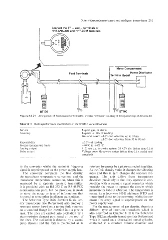
I Connect the BT + and - terminals or
HHT.ANALOG and HHT-COM terminals
U
--
Meter Compartment
Field Terminals Power Distributor
Figure 13.21 Arrangement of the measurement circuit for avortex flowmeter Courtesyof Yokogawa Corp of America Inc
Table 13.11 Outline performance specifications of theYEWFLO vortex flowmeter
Service Liquid, gas, or steam
Accuracy Liquids: f1.0% of reading
Gas and steam: h1.0Y0 for velocities up to 35mk
11.5% for velocities from 35 to 8Qmk
Repeatability &0.2% of reading
Process temperature limits -40°C to +4OO0C
Analog output 4-20 mA d.c. two-wire system, 2042 V d.c. (delay time 0.5 s)
Pulse output Voltage pulse, three-wire system (delay time 0.5 s; scaled and
unscaled)
-~ -
to the converter whilst the resonant frequency resonant frequency by a phase-corrected amplifier.
signal is superimposed on the power supply lead. As the fluid density varies it changes the vibrating
The converter computes the line density, mass and this in turn changes the resonant fre-
the transducer temperature correction, and the quency. The unit differs from transmitters
transducer temperature correction, when this is described previously in that they operate in con-
measured by a separate pressure transmitter. junction with a separate signal converter which
It is provided with an RS 232 C or RS 485/422 provides the power to operate the circuits which
communication port, but no provision is made maintain the tube in vibration. The temperature is
to store the range or type of information that sensed by a four-wire 1000 platinum RTD and
is stored in some other intelligent transmitters. transmitted direct to the converter, whilst the res-
The Sclartron Type 7826 insertion liquid den- onant frequency signal is superimposed on the
si~7 transducers (see References) also employ a power supply lead.
resonant sensor based on a tuning fork mounted For the measurement of gas density, there is a
on a standard flange for insertion into a pipe or different type of insertion transducer which is
tank. The tines are excited into oscillation by a also described in Chapter 8. It is the Solartron
piezo-resistive element positioned at the root of Type 7812 gas density transducer (see References)
the tines. The oscillation is detected by a second which is based on a thin-walled metal cylinder,
piezo element and the fork is maintained at its contained in a constant volume chamber and