
Page 231 - Instrumentation Reference Book 3E
P. 231
Microprocessor-based and intelligent flowmeters 215
Data which are stored in the non-volatile mem- lntearallv mounted
ory include: transmitter
(1) Transmitter model number
(2) Line size
(3) Material of construction
(4) Sensor limits
(5) Minimum span
(6) Transmitter software revision level.
13.7.2 Electromagnetic flowmeters
Since the first applications of electromagnetic
flowmeters in the process industries, during the
mid-1950s, their design has progressed through
several evolutionary phases and their perform-
ance has now reached a very high standard. As
described in Chapter 1, their principal attributes
are that the head loss is negligible and the output
signal is proportional to flow rate over a very wide
range. The sensor is relatively insensitive to vel-
ocity profile and hence to changes in viscosity, with
the result that the installation requirements are
less severe than for most other types of flowmeter.
Provided that the fluid conductivity is above a
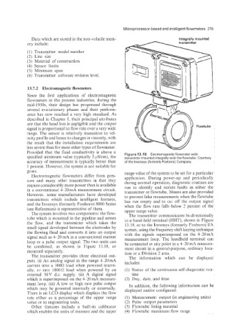
Figure 13.1 8 Electromagnetic flowmeter with
specified minimum value (typically 5 pS/cm), the transmitter mounted integrally with the flowtube. Courtesy
accuracy of measurement is typically better than of the lnvensys (formerly Foxboro) Company.
1 percent. However, the system is not suitable for
gases. range value of the system to be set for a particular
Electromagnetic flowmeters differ from pres- application. During power-up and periodically
sure and many other transmitters in that they during normal operation. diagnostic routines are
require considerably more power than is available run to identify and isolate faults in either the
in a conventional 4-2Q mA measurement circuit. transmitter or flowtube. Means are also provided
However. some manufacturers have developed to prevent false measurements when the flowtube
transmitters which include intelligent features, has run empty and to cu: off the output signal
and the Invensys (formerly Foxboro) 8000 Series when the flow rate falls below 2 percent of the
(see References) is representative of them. upper range value.
The system involves two components: the flow- The transmitter communicates bi-directionally
tube which is mounted in the pipeline and senses to a hand-held terminal (HHT), shown in Figure
the flow, and the transmitter which takes the 13.19, or to the Invensys (formerly Foxboro) I/A
small signal developed between the electrodes by system, using the frequency shift keying technique
the flowing fluid and converts it into an output with the signals superimposed on the 4-20 mA
signal such as 420 niA in a conventional current measurement loop. The handheld terminal can
loop or a pulse output signal. The two units can be connected at any point in a 4-20 mA measure-
be combined, as shown in Figure 13.18, or ment circuit in a general-purpose, ordinary loca-
mounted separately. tion or a Division 2 area.
The transmitter provides three electrical out- The information which can be displayed
puts. (i) An analog signal in the range 4-20mA includes:
current into a 3000 load when powered intern-
ally, or into 18009 load when powered by an (1) Status of the continuous self-diagnostic rou-
external 50V d.c. supply. (ii) A digital signal tine
which is superimposed on the 4-20 mA measure- (2) Day, date, and time.
ment loop. (iii) A low or high rate pulse output In addition, the following information can be
which may be powered internally or externally. displayed and/or configured:
There is an LCD display which displays the flow
rate either as a percentage of the upper range (1) Measurement output (in engineering units)
value or in engineering units. (2) Pulse output parameters
Other features include a built-in calibrator (3) Flowtube lining material
which enables the units of measure and the upper (4) Flowtube maximum flow range