
Page 226 - Instrumentation Reference Book 3E
P. 226
210 Microprocessor-based and intelligent transmitters
protectors.
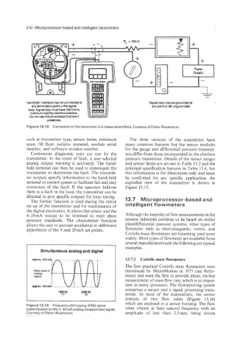
Figure 13.13 Connection of the transmitter in a measurement loop. Courtesy of Fisher-Rosemount
such as transmitter type, sensor limits, minimum The three versions of the transmitter have
span, fill fluid, isolator material, module serial many common features but the sensor modules
number, and software revision number. for the gauge and differential pressure transmit-
Continuous diagnostic tests are run by the ters differ from those incorporated in the absolute
transmitter. In the event of fault, a user-selected pressure transmitter. Details of the sensor ranges
analog output warning is activated. The hand- and sensor limits are set out in Table 13.3 and the
held terminal can then be used to interrogate the principal specification features in Table 13.4, but
transmitter to determine the fault. The transmit- this information is for illustration only and must
ter outputs specific information to the hand-held be confirmed for any specific application. An
terminal or control system to facilitate fast and easy exploded view of the transmitter is shown in
correction of the fault. If the operator believes Figure 13.15.
there is a fault in the loop, the transmitter can be
directed to give specific outputs for loop testing. 13.7 Microprocessor-based and
The format function is used during the initial
set-up of the transmitter and for maintenance of intelligent flowmeters
the digital electronics. It allows the sensor and the
4-20mA output to be trimmed to meet plant Although the majority of flow measurements in the
pressure standards. The characterize function process industries continue to be based on orifice
allows the user to prevent accidental or deliberate plate/differential pressure systems, other types of
adjustment of the 4 and 20mA set points. flowmeter such as electromagnetic, vortex, and
Coriolis mass flowmeters are becoming used more
widely. Most types of flowmeter are available from
several manufacturers and the following are typical
I
Simultaneous analog and digital examples.
approx. +OS mA 13.7.1 Coriolis mass flowmeters
The first practical Coriolis mass flowmeters were
introduced by MicroMotion in 1977 (see Refer-
ences) and were the first to provide direct, on-line
measurement of mass flow rate, which is so impor-
______
appror.Q.5mA[ ........... u..J !.!. tant in many processes. The flowmetering system
comprises a sensor and a signal processing trans-
1203 Hr 2200 Hr I mitter. In most of the transmitters, the sensor
'1 " '0' consists of two flow tubes (Figure 13.16)
which are enclosed in a sensor housing. The flow
Figure 13.14 Frequencyshift keying (FSK) signal
superimposed on the 4-20 mA analog measurement signal. tubes vibrate at their natural frequency with an
Courtesy of Fisher-Rosemount. amplitude of less than 2.5 mm, being driven