
Page 223 - Instrumentation Reference Book 3E
P. 223
Microprocessor- based and intelligent temperature transmitters 207
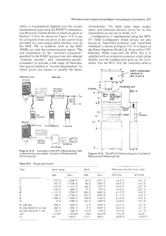
ability to communicate digitally over the current characteristic. The input types, input ranges.
measurement loop using the HART Communica- spans, and minimum absolute errors for the two
tion Protocol, further details of which are given in transmitters are set out in Table 13.2.
Section 13.10.4. As shown in Figure 13.8, it can Configuration is implemented using the MTL
be configured from any point in the current loop 611 Field Configurator (these devices are also
provided any intervening safety barriers, such as known as "hand-held terminals" and "hand-held
the MTL 706. or isolators, such as the MTL interfaces"), shown in Figure 13.9. It is based on
30465 can pass the communication signals. The the Psion Organizer Model LZ. fitted with a GNF
unit implements all the "universal commands" Interface. When used with the MTL 414, it is
specified by the HART protocol and also selected supplied with an extension connector which plugs
"common practice" and "transmitter-specific'' directly into the configuration port on the trans-
commands to provide a full range of functions. mitter. For the MTL 418, the extension cable is
One special function is "custom linearlization" by
which points are chosen to modify the sensor TI CNF41 configuration
interface for
Hazardous area Safe area MTL 4141418
MTL41E
x
+32 --rl
Vt
1-5V
MTL3046B
Figure 13,8 lnstallationof the MTL418transmitter, with
a safety barrier or an isolator. Courtesy of Measurement Figure 13.9 The MTL611 field configurator. Courtesyof
Technology Ltd. MeasurementTechnology Ltd.
Table 13.2 Range specification
qpe Input vaiige
E -175°C fi000"C 50 "C 1175 "C f0.4 "C i0.2 'C
J -185°C f1200'C 60 "C 1385 "C h0.4 "C =0.3"C
K -175°C +1372T 60 "C 1547°C &0.4 "C *0.2"C
T -170°C +400'C 75 "C 570°C &0.4 "C 3.2 "C
R -125°C +1768 'C 360°C 1643 "C fl.1"C f0.6 "C
S 1150°C t1768"C 370 "C 1618°C f1.2'C &0.6 "C
B +700"C 11820°C 700°C 1120°C f1.6"C i0.8 "C
N 0°C -1300°C 180 'C 1300°C f0.4"C i0.2 'C
Pt 100 IEC -100 "C +850 ' C 6 "C 1050°C f0.2 "C hO.1 'C
Pt 100 MINCO 11-100 -200 "C +850 ' C 6 'C 1050°C f0.2 "C tO.l ;c
Ni 120 MINCO 7-120 -70°C +300"C 3.5 "C 370°C f0.2 "C +o. L 'C
mV -15mV -150mV 3 mV 165mV f16pV 58 pV
(1 9R 1500 R 2.5 n 500 R f0.05 R 2ko.025 n