
Page 228 - Instrumentation Reference Book 3E
P. 228
212 Microprocessor-based and intelligent transmitters
Table 13.3 Range limits for the sensor modules for the differential, gauge, and absolute pressure transmitters
Sensor Model 3501 CD differential pressure Model 3501 CG gauge presswe Model 3501A absolute pressure
code transmitter transmitter transmitter
Minimum Maximum Minimum Maximurn Minimum Maximum
0 NA NA NA NA 1.15kPa 34.6 kPa
1 210Pa 6220 Pa NA NA 6.89 kPa 207 kPa
2 2.07 kPa 62.2 kPa 2.07 kPa 62.2 kPa 34.5 kPa 1.034MPa
3 8.28 kPa 248 kPa 8.28 kPa 248 kPa 186kPa 5.51 MPa
4 69.0 kPa 2070 kPa 69.0 kPa 2070 kPa 913kPa 27.6 MPa
5 460 kPa 13.8 MPa 460 kPa 13.8 MPa NA NA
NA: not available.
Table 13.4 Outline performance specifications of the 3501C series of transmitters
Service Liquid or gas
output Two-wire &20mA d.c. with the digital value of the
process variable superimposed
Power supply 10.5-55V d.c.
Temperature limits Process: -40°C to +llO”C
Ambient: -40°C to +85”C
Damping Adjustable from 0 to 16 s
Accuracy f0.075% of spans for spans from 1:l to 1O:l of URL
Stability Range 2 & 3: *0.1% of URL for 12 months
Range 4 & 5: +0.2% of URL for 12 months
RIGHT POSITION DETECTOR ’
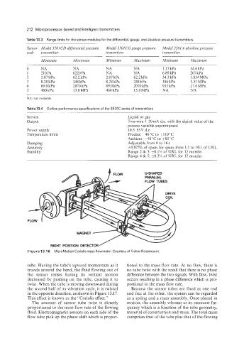
Figure 13.1 6 MicroMotion Coriolis mass flowmeter. Courtesyof Fisher-Rosemount.
tube. Having the tube’s upward momentum as it tional to the mass flow rate. At no flow, there is
travels around the bend, the fluid flowing out of no tube twist with the result that there is no phase
the sensor resists having its vertical motion difference between the two signals. With flow, twist
decreased by pushing on the tube, causing it to occurs resulting in a phase difference which is pro-
twist. When the tube is moving downward during portional to the mass flow rate.
the second half of its vibration cycle, it is twisted Because the sensor tubes are fixed at one end
in the opposite direction, as shown in Figure 13.17. and free at the other, the system can be regarded
This effect is known as the “Coriolis effect.” as a spring and a mass assembly. Once placed in
The amount of sensor tube twist is directly motion, the assembly vibrates as its resonant fre-
proportional to the mass flow rate of the flowing quency which is a function of the tube geometry,
fluid. Electromagnetic sensors on each side of the material of construction and mass. The total mass
flow tube pick up the phase shift which is propor- comprises that of the tube plus that of the flowing