
Page 225 - Instrumentation Reference Book 3E
P. 225
Microprocessor-based and intelligent pressure and differential transmitters 209
_-- ---- ------ 1
~r--------------------
I Sensor Module II Electmnlcs Module I
Interlace
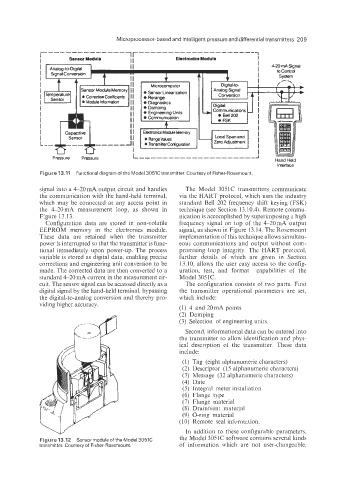
Figure 13.11 Functional diagram of the Model 3051C transmitter. Courtesyof Fisher-Rosemount.
signal into a 4-20 mA output circuit and handles The Model 305 1 C transmitters communicate
the communication with the hand-held terminal, via the HART protocol, which uses the industry
which may be connected at any access point in standard Bell 202 frequency shift keying (FSK)
the 4-20mA measurement loop, as shown in technique (see Section 13.10.4). Remote commu-
Figure 13.13. nication is accomplished by superimposing a high
ConfigJration data are stored in non-volatile frequency signal on top of the 4-20mA output
EEPROM memory in the electronics module. signal, as shown in Figure 13.14. The Rosemount
These data are retained when the transmitter implementation of this technique allows simultan-
power is interrupted so that the transmitter is func- eous communications and output without com-
tional immediately upon power-up. The process promising loop integrity. The HART protocol,
variable is stored as digital data, enabling precise further details of which are given in Section
corrections and engineering unit conversion to be 13.10, allows the user easy access to the config-
made. The corrected data are then converted to a uration, test, and format capabilities of the
standard 4-20 mA current in the measurement cir- Model 3051C.
cuit. The sensor signal can be accessed directly as a The configuration consists of two parts. First
digital signal by the hand-held terminal, bypassing the transmitter operational parameters are set,
the digital-to-analog conversion and thereby pro- which include:
viding higher accuracy.
(1) 4 and 20mA points
(2) Damping
(3) Selection of engineering units.
Second; informational data can be entered into
the transmitter to allow identification and phys-
ical description of the transmitter. These data
include:
(1) Tag (eight alphanumeric characters)
(2) Descriptor (1 5 alphanumeric characters)
(3) Message (32 alphanumeric characters)
(4) Date
(5) Integral meter instaliation
(6) Flange type
(7) Flange material
(8) Drainlvent material
(9) O-ring material
(10) Remote seal information.
In addition to these configurable parameters,
Figure 13.12 Sensor moduleof the Model 3051C the Model 305 1C software contains several kinds
transmitter. Courtesy of Fisher-Rosemount. of information which are not user-changeable,