
Page 224 - Instrumentation Reference Book 3E
P. 224
208 Microprocessor-based and intelligent transmitters
fitted with two clips which can be connected at 13.6 Microprocessor-based and
any access point in the measurement loop in intelligent pressure and
either hazardous or safe areas. differential transmitters
Configuration information is presented on a
four-line dot matrix display with 20 characters Conventional pressure and differential pressure
on each line. all options being selected from transmitters are described in Chapter 9, but now
menus and submenus. Testing and monitoring there are numerous microprocessor-based and
can also be carried out with the configurator. intelligent versions. The Rosemount Model
The range and versatility of the options are 3051C (see References) is an excellent example
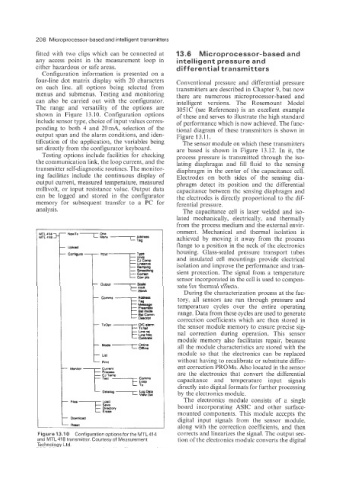
shown in Fiyre 13.10. Configuration options of these and serves to illustrate the high standard
include sensor type, choice of input values corres- of performance which is now achieved. The func-
ponding to both 4 and 20mA, selection of the tional diagram of these transmitters is shown in
output span and the alarm conditions, and iden- Figure 13.1 1.
tification of the application, the variables being The sensor module on which these transmitters
set directly from the configurator keyboard. are based is shown in Figure 13.12. In it, the
Testing options include facilities for checking process pressure is transmitted through the iso-
the communication link, the loop current, and the lating diaphragm and fill fluid to the sensing
transmitter self-diagnostic routines. The monitor- diaphragm in the center of the capacitance cell.
ing facilities include the continuous display of Electrodes on both sides of the sensing dia-
output current, measured temperature, measured phragm detect its position and the differential
millivolt, or input resistance value. Output data capacitance between the sensing diaphragm and
can be logged and stored in the configurator the electrodes is directly proportional to the dif-
memory for subsequent transfer to a PC for ferential pressure.
analysis. The capacitance cell is laser welded and iso-
lated mechanically, electrically, and thermally
from the process medium and the external envir-
onment. Mechanical and thermal isolation is
achieved by moving it away from the process
flange to a position in the neck of the electronics
housing. Glass-sealed pressure transport tubes
and insulated cell mountings provide electrical
isolation and improve the performance and tran-
sient protection. The signal from a temperature
sensor incorporated in the cell is used to compen-
sate for thermal effects.
r Output Mm* During the characterization process at the fac-
tory, all sensors are run through pressure and
temperature cycles over the entire operating
range. Data from these cycles are used to generate
correction coefficients which are then stored in
the sensor module memory to ensure precise sig-
nal correction during operation. This sensor
module memory also facilitates repair, because
all the module characteristics are stored with the
module so that the electronics can be replaced
without having to recalibrate or substitute differ-
ent correction PROMS. Also located in the sensor
are the electronics that convert the differential
capacitance and temperature input signals
directly into digital formats for further processing
by the electronics module.
The electronics module consists of a single
board incorporating ASIC and other surface-
t mounted components. This module accepts the
digital input signals from the sensor module,
along with the correction coefficients. and then
Figure 13.10 Configuration optionsforthe MTL414 corrects and linearizes the signal. The output sec-
and MTL 418 transmitter. Courtesy of Measurement tion of the electronics module converts the digital
Technology Ltd.