
Page 234 - Instrumentation Reference Book 3E
P. 234
218 Microprocessor-based and intelligent transmitters
damping, etc. Although the transmitter would
almost certainly include a secondary temperature
sensor, it is unlikely that the temperature mea-
surement signal would be sufficiently close to that
of the process fluid for it to be used for that
purpose.
A practical difficulty which is likely to arise
when using a differential pressure transmitter in
this way is that the process fluid in these connec-
tions is static and therefore may become blocked
due to sedimentation, or solidification of the pro-
cess fluid as a result of changes in ambient condi-
tions. This can be mitigated by using a differential
pressure transmitter fitted with pressure seals and
capillary connections, as shown in Figure 13.23.
The disadvantages of this arrangement are the
higher cost of a transmitter fitted with the pres-
sure seals and the reduced accuracy of the system.
An alternative approach is to use two flange
mounted pressure transmitters, mounted a known
vertical distance apart, as shown in Figure 13.24.
In this case, the pressure difference is determined
by subtracting the pressure measured at the upper
level from that measured at the lower level.
Thanks to modern multivariable technology a
third option has become available only in the past
few years. The Smar DT301 is a single integrated
smart device with an insertion probe having large
diaphragms and a true process temperature sen-
sor to overcome the above-mentioned problems
and at the same time compute density, referred
density, and concentration using the onboard
microprocessor. For either method to be success-
ful, it is essential to ensure that the liquid level
does not fall below the position of either the upper
pressure seal or the connection to the upper pres-
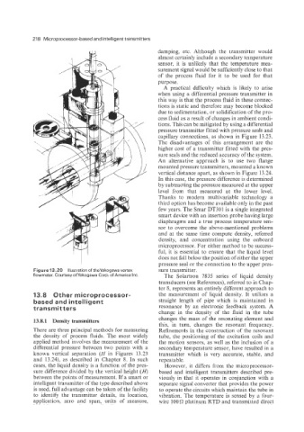
Figure 13.20 Illustration of theYokogawa vortex sure transmitter.
flowmeter. Courtesy ofYokogawa Corp. of America Inc. The Solartron 7835 series of liquid density
transducers (see References), referred to in Chap-
ter 8, represents an entirely different approach to
13.8 Other microprocessor- the measurement of liquid density. It utilizes a
based and intelligent straight length of pipe which is maintained in
transmitters resonance by an electronic feedback system. A
change in the density of the fluid in the tube
13.8.1 Density transmitters changes the mass of the resonating element and
this, in turn, changes the resonant frequency.
There are three principal methods for measuring Refinements in the construction of the resonant
the density of process fluids. The most widely tube, the positioning of the excitation coils and
applied method involves the measurement of the the motion sensors, as well as the inclusion of a
differential pressure between two points with a secondary temperature sensor, have resulted in a
known vertical separation (N in Figures 13.23 transmitter which is very accurate, stable, and
and 13.24), as described in Chapter 8. In such repeatable.
cases, the liquid density is a function of the pres- However, it differs from the microprocessor-
sure difference divided by the vertical height (H) based and intelligent transmitters described pre-
between the points of measurement. If a smart or viously in that it operates in conjunction with a
intelligent transmitter of the type described above separate signal converter that provides the power
is used, full advantage can be taken of the facility to operate the circuits which maintain the tube in
to identify the transmitter details, its location, vibration. The temperature is sensed by a four-
application, zero and span, units of measure, wire 100 R platinum RTD and transmitted direct