
Page 275 - Instrumentation Reference Book 3E
P. 275
Measurement techniques: electrical 259
Ceramic tube
Platinum wire.
Element is
miniature coil
Guard tub; with
I
Ceramic rod ventilc7ting holes
(C) (dl (e)
Silver clad Pins plated Stainless
High temperature capper. silver. or steel head
sealing compound pure nickel leads
Sensing I
element
\
Thermoweil
or pocket
metalseals
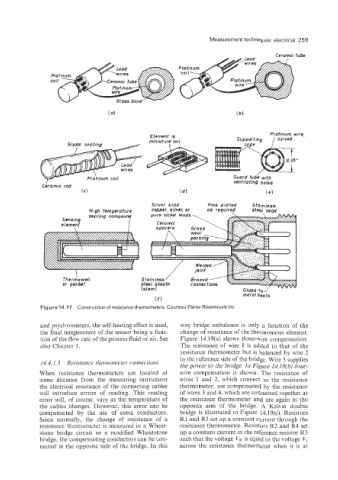
Figure 14.17 Construction of resistance thermometers. Courtesy Fisher-Rosemount Inc
and psychrometers, the self-heating effect is used, way bridge unbalance is only a function of the
the final temperature of the sensor being a func- change of resistance of the thermometer element.
tion of the flow rate of the process fluid or air. See Figure 14.19(a) shows three-wire compensation.
also Chapter 1. The resistance of wire 1 is added to that of the
resistance thermometer but is balanced by wire 2
in the reference side of the bridge. Wire 3 supplies
14.4.1.3 Resistance tlzeimometea coiznections
the power to the bridge. In Figure 14.19(b) four-
When resistance thermometers are located at wire compensation is shown. The resistance of
some distance from the measuring instrument wires 1 and 2, which connect to the resistance
the electrical resistance of the connecting cables thermometer, are compensated by the resistance
will introduce errors of reading. This reading of wires 3 and 4, which are connected together at
error will, of course, vary as the temperature of the resistance thermometer and are again in the
the cables changes. However, this error can be opposite arm of the bridge. A Kelvin double
compensated by the use of extra conductors. bridge is illustrated in Figure 14.19(c). Resistors
Since normally, the change of resistance of a R1 and R3 set up a constant current through the
resistance thermometer is measured in a Wheat- resistance thermometer. Resistors R2 and R4 set
stone bridge circuit or a modified Wheatstone up a constant current in the reference resistor R5
bridge, the compensating conductors can be con- such that the voltage VR is equal to the voltage Vt
nected in the opposite side of the bridge. In this across the resistance thermometer when it is at