
Page 278 - Instrumentation Reference Book 3E
P. 278
262 Temperature measurement
Most thermistors have a specified resistance at
20 "C or 25 "C. To determine the resistance at any
other temperature equation (14.16) is used:
(14.16)
where RI is resistance of thermistor at tempera-
ture tl("C) and Rz is resistance of thermistor at
temperature tZ(OC).
Thermistors are available described as curve-
matched. These devices are manufactured to
fine tolerances and are interchangeable with an
error of less than f0.2 percent. However, they
are expensive and are only available in a limited
range of formats.
In general most thermistors are manufactured
with tolerances of 10 to 20 percent. Instrumenta-
tion for use with these devices must have provi-
sion for trimming out the error. Thermistors do I 1
not have the stability of platinum resistance therm- tR
ometers. Their characteristics tend to drift with Temperature
time. Drifts of up to 0.1 "C or more can be Figure 14.20 Resistancetemperature characteristic for
expected from some types over a period of some PTC thermistor,
months.
14.4.2.2 Positive tenzperatrire coefficient
thermistors
Positive temperature coefficient (PTC) thermis-
tors are manufactured from compounds of bar-
ium, lead, and strontium titanates. PTC
thermistors are primarily designed for the protec-
tion of wound equipment such as transformers
and motors. The characteristics of these devices
have the general shape shown in Figure 14.20.
The resistance of PTC thermistors is low and
relatively constant with temperature at low tem- :urrent 43
perature. At temperature TR the increase of resist-
ance with temperature becomes very rapid. TR is
the reference or switching temperature.
In use, PTC thermistors are embedded in the
windings of the equipment to be protected. They
are connected in series with the coil of the equip-
ment contractor or protection relay. If the tem-
perature of the windings exceeds temperature TR
the current becomes so small that power is dis-
connected from the equipment.
Voltage
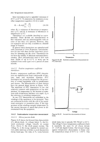
14.4.3 Semiconductor temperature measurement Figure 14.21 Forward bias characteristic of silicon
diode.
14.4.3.1 Silicon junction diode
Figure 14.21 shows the forward bias characteristic
of a silicon diode. At voltages below Vf, the for- diode types, but is typically 500-700 mV at 20 "C.
ward conduction voltage, virtually no current The voltage Vf has a temperature coefficient which
flows. Above Vf the diode passes current. The is essentially the same for all silicon devices
voltage VF is the energy required by current car- of -2mV per degree Celsius. The forward voltage
riers, either electrons or holes, to cross the junction against temperature characteristic is linear over
energy band gap. The value of VF varies between the temperature range of 50°C to +15OoC. This